---
translationKey: microchannel-cold-plate-manufacturing
lang: en
slug: microchannel-cold-plate-manufacturing
title: 'How Microchannel Cold Plates Are Machined: Geometry and Manufacturability'
description: A structured DFM guide to microchannel cold plates, covering channel geometry, process routes, flow distribution, burr control, cleaning, sealing, validation, and production readiness.
publishDate: 2026-07-30
updateDate: 2026-07-30
draft: false
featured: false
category: process-knowledge
industries:
- liquid-cooling
tags:
- microchannel cold plate
- cold plate machining
- CNC micro-milling
- diffusion bonding
- liquid cooling
- manufacturability
author: Zhongde Precision Engineering Team
reviewedBy: Zhongde Precision Engineering Team
directAnswer: A microchannel cold plate does not become better simply because every channel is made smaller. Channel width, depth, aspect ratio, fin thickness, base thickness, and flow distribution must be selected together with flow rate, pressure drop, material, manufacturing method, cleanliness, sealing, and inspection capability. CNC micro-milling is often the most flexible prototype route; skiving can suit regular parallel fins; etching or sheet forming can suit dense two-dimensional paths; and stacked thin plates with diffusion bonding can create multilayer three-dimensional structures. The goal is not the smallest possible feature, but a design that can be machined, cleaned, sealed, inspected, and produced consistently.
relatedPages:
- /en/ai-server-liquid-cooling-parts-machining
- /en/precision-machining
- /en/quality/manufacturing-process
- /en/quality/inspection-equipment
relatedArticles:
- ai-server-cold-plate-manufacturing-processes
- aluminum-vs-copper-liquid-cold-plates
faq:
- question: Do smaller microchannels always improve cooling?
answer: No. A smaller hydraulic diameter can improve local heat transfer, but it also increases pressure drop, pump demand, sensitivity to machining variation, burrs, and clogging. Thermal performance, pressure drop, and manufacturing stability must be balanced.
- question: Can CNC machining produce microchannel cold plates?
answer: Yes, especially for prototypes and designs that may change. Channel width, aspect ratio, tool rigidity, chip evacuation, burrs, and machining time must still be verified through trials.
- question: Must a microchannel cold plate be made from copper?
answer: No. Copper can improve local heat spreading, but aluminum microchannel cold plates are also possible. Material selection should consider heat flux, weight, cost, coolant compatibility, and joining method.
- question: Does passing a leak test prove that the microchannels are acceptable?
answer: No. A leak test verifies detectable leakage only. It does not prove that channels are free of local blockage, that branch flow is uniform, or that pressure drop meets the system requirement.
- question: What information is needed for a microchannel cold plate RFQ?
answer: Provide heat load, contact area, flow rate, allowable pressure drop, coolant, 2D drawings, 3D model, channel dimensions, material, sealing method, operating pressure, leakage requirement, cleanliness, expected volume, and validation requirements.
---
## Direct answer
The engineering objective is not to make every channel as small as possible. It is to create enough effective heat-transfer area while keeping pressure drop, pump demand, manufacturing risk, and production cost under control.
01
Smaller channels
May improve local heat transfer, but increase pressure drop, clogging, and machining risk.
02
Higher aspect ratio
Reduces tool rigidity and makes chip evacuation and dimensional consistency harder.
03
Uneven distribution
Can starve some branches even when every channel dimension is within tolerance.
04
Machining completed
Does not mean deburring, cleaning, sealing, and validation are complete.
The manufacturing route should follow a clear chain: thermal and fluid requirements → geometry → process selection → cleanliness and sealing → flow, pressure-drop, leak, and production validation.
---
## 1. What qualifies as a microchannel cold plate
A microchannel cold plate uses a dense group of narrow channels or fine fins in the heat-source region to increase effective heat-transfer area and shorten the conduction path. The difference from a conventional serpentine channel is not only size. Channel count, manifolding, pressure drop, cleanliness, and dimensional variation have a much stronger influence on performance.
Reducing hydraulic diameter can improve heat transfer, but it also increases flow resistance. The design must therefore define the heat-source map, available flow and pump pressure, branch-flow uniformity, manufacturability, cleanability, sealability, and sensitivity of pressure drop to dimensional variation.
---
## 2. Six dimensions that control manufacturability
CHANNEL WIDTH
Very thin fins are more vulnerable to machining damage, joining distortion, and pressure load.
BASE THICKNESS
Base thickness
A thick base adds thermal resistance; a thin base reduces stiffness, flatness, and pressure margin.
SEALING LAND
Sealing land
The outer edge, ports, weld zone, or seal groove needs enough material outside the channels.
| Design change | Possible benefit | Main manufacturing risk |
| ----------------- | ------------------------------------- | -------------------------------------------------------- |
| Narrower channels | More heat-transfer interface per area | Tool limits, larger relative burrs, clogging sensitivity |
| Deeper channels | More flow and heat-transfer area | Chip evacuation, wall accuracy, higher aspect ratio |
| Thinner fins | More fins per area | Fin deformation, damage, joining distortion |
| Thinner base | Shorter conduction path | Flatness, pressure strength, fixturing distortion |
| More branches | Wider heat-source coverage | Maldistribution, cleaning and inspection difficulty |
---
## 3. Manufacturing routes for microchannels
Microchannels are not produced by one process alone. The route should be selected according to channel regularity, blind-channel requirements, channel count, material, prototype quantity, and production scale.
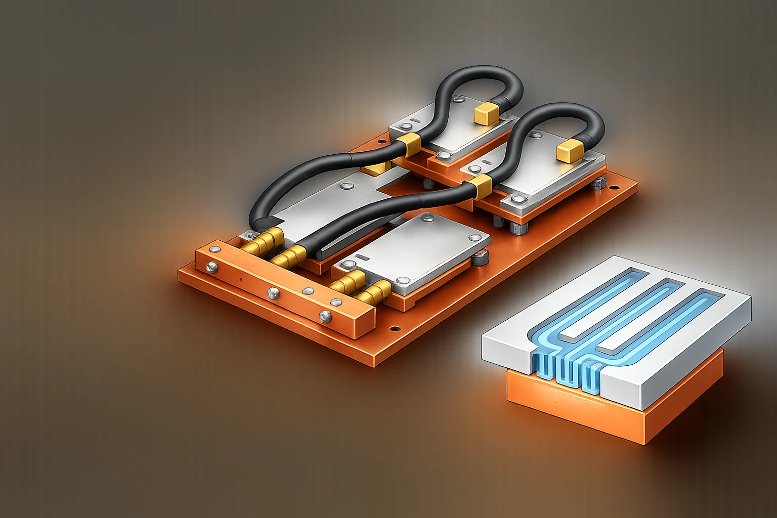
The modular assembly illustrates a multi-cold-plate system. The cutaway shows that performance depends on channel organization, heat-source contact, and coolant distribution—not simply on making every passage narrower.
A
CNC micro-milling
Best for prototypes, blind channels, local complexity, and frequent design changes.
B
Skiving
Suitable for regular parallel micro-fins with good efficiency but limited geometry freedom.
C
Etching / sheet forming
Useful for dense two-dimensional paths that are later stacked and joined.
D
Stacked plates / diffusion bonding
Enables multilayer three-dimensional short paths, with stricter alignment and bonding control.
| Route | Geometry freedom | Prototype flexibility | Production potential | Main risk |
| ------------------------------------- | ---------------: | --------------------: | -------------------: | ------------------------------------------------ |
| CNC micro-milling | High | High | Medium | Tool life, burrs, cycle time |
| Skiving | Low to medium | Medium | High | Fin consistency, geometry limits |
| Chemical etching / sheet forming | Medium | Medium | High | Etch bias, sheet thickness, joining |
| Wire EDM and special processes | Limited | Medium | Low to medium | Through-feature limits, speed, surface condition |
| Stacked sheets with diffusion bonding | Very high | Low to medium | Medium to high | Layer alignment, bond integrity, distortion |
A published Fujikura stacked cold plate uses patterned thin metal plates and diffusion bonding to form dense, short three-dimensional flow paths. In that specific design, thermal resistance was reported to be more than 20% lower than a conventional cold plate of the same size. The key lesson is that better flow organization can be more important than endlessly thinning one conventional fin structure.
---
## 4. Why the inlet, outlet, and manifold matter
Even if every individual channel is identical, the cold plate can still perform poorly when the inlet pressure field is uneven. Channels close to the inlet may carry too much flow while distant branches are starved.
The DFM review should cover inlet and outlet position, manifold cross-section, branch length and resistance, local heat-source reinforcement, dead zones, trapped air, and whether the planned flow test can reveal branch abnormalities.
---
## 5. Burrs, cleanliness, and blockage risk
01Cutting trialVerify tools, parameters, radii, and burr shape
02Channel machiningControl tool life, chip evacuation, and drift
03DeburringAvoid secondary damage to fins and sealing lands
04Cleaning and dryingRemove particles, oil, and cleaning residue
05Pre-seal protectionPrevent the internal path from being contaminated again
06Flow verificationDetect local blockage and abnormal pressure drop
Small burrs and particles that are acceptable in conventional machining can become blockage sources in a microchannel. Cleanliness must be designed from cutting and handling onward, not added as a final wash only.
---
## 6. Cover sealing, joining, and distortion control
| Sealing or joining method | Main advantage | Main risk |
| ------------------------------- | -------------------------------------- | ---------------------------------------------- |
| Mechanical cover and seal | Flexible and serviceable | Groove size, compression, cover stiffness |
| Vacuum brazing | Suitable for aluminum split structures | Filler flow, blockage, thermal distortion |
| Diffusion bonding | Suitable for stacked multilayer paths | Surface preparation, alignment, bond integrity |
| Welding / friction-stir joining | Strong local joining capability | Heat input, path limits, post-join distortion |
The plan should define joining-gap control, filler migration, final contact-face machining, port shift, inspection access, and whether internal defects can be detected.
---
## 7. Verifying dimensions, flow, pressure drop, and sealing
Geometry
Channel width and depth, fin and base thickness, flatness, and port position.
Internal quality
Burrs, particles, blockage, joining defects, and channel continuity.
Fluid performance
Total flow, pressure drop, branch distribution, and trends across operating points.
Reliability
Leak, proof pressure, thermal cycling, vibration, corrosion, and service conditions.
| Validation | Purpose | What it cannot replace |
| ------------------------- | ----------------------------------------- | ------------------------------------- |
| Dimensional inspection | Confirms geometry against drawing | Does not prove no blockage |
| Leak test | Confirms no detectable leakage | Does not prove uniform flow |
| Proof-pressure test | Confirms pressure strength | Does not prove thermal performance |
| Flow / pressure-drop test | Detects resistance anomalies | Does not fully prove heat transfer |
| Thermal test | Confirms temperature or resistance target | Does not replace lifetime reliability |
---
## 8. Re-evaluating the design from prototype to production
PROTOTYPE
Prototype
Verify thermal behavior, tool accessibility, burr form, and the basic sealing route.
ENGINEERING
Engineering validation
Freeze CTQs, tolerances, cleaning, leak, flow, pressure-drop, and thermal methods.
PRODUCTION
Production readiness
Establish tool replacement, fixtures, process capability, sampling, and traceability.
A successful CNC prototype does not automatically prove that the production route is stable. Cycle time, tool life, cleaning repeatability, joining yield, inspection cost, and alternative forming or stacked routes must be reviewed again.
---
## 9. Information needed for RFQ and DFM review
| Information group | What to provide |
| -------------------- | --------------------------------------------------------------------------------- |
| Thermal design | Heat load, heat flux, contact area, target temperature rise or thermal resistance |
| Fluid conditions | Coolant, target flow, allowable pressure drop, inlet temperature, pump capability |
| Geometry | 2D drawing, 3D model, channel width/depth, fin and base thickness |
| Material and joining | Alloy, temper, cover, brazing or diffusion-bonding requirement |
| Reliability | Operating pressure, proof pressure, leak rate, thermal cycle, corrosion condition |
| Program conditions | Prototype quantity, annual volume, takt time, inspection ratio, traceability |
## FAQs
### Do smaller microchannels always improve cooling?
No. A smaller hydraulic diameter can improve local heat transfer, but it also increases pressure drop, pump demand, sensitivity to machining variation, burrs, and clogging. Thermal performance, pressure drop, and manufacturing stability must be balanced.
### Can CNC machining produce microchannel cold plates?
Yes, especially for prototypes and designs that may change. Channel width, aspect ratio, tool rigidity, chip evacuation, burrs, and machining time must still be verified through trials.
### Must a microchannel cold plate be made from copper?
No. Copper can improve local heat spreading, but aluminum microchannel cold plates are also possible. Material selection should consider heat flux, weight, cost, coolant compatibility, and joining method.
### Does passing a leak test prove that the microchannels are acceptable?
No. A leak test verifies detectable leakage only. It does not prove that channels are free of local blockage, that branch flow is uniform, or that pressure drop meets the system requirement.
### What information is needed for a microchannel cold plate RFQ?
Provide heat load, contact area, flow rate, allowable pressure drop, coolant, 2D drawings, 3D model, channel dimensions, material, sealing method, operating pressure, leakage requirement, cleanliness, expected volume, and validation requirements.