
01 / RIGIDITY
Frame rigidity
Preserve the relationship between side plates, bearing bores and the spool axis under peak load

FISHING REEL & TACKLE PARTS MACHINING
From lightweight frames, precision spools and transverse shaft systems to drag transmission and marine-resistant finishes, we build a verifiable, production-ready manufacturing system for high-load offshore reels.
02 / LOAD BECOMES PRECISION
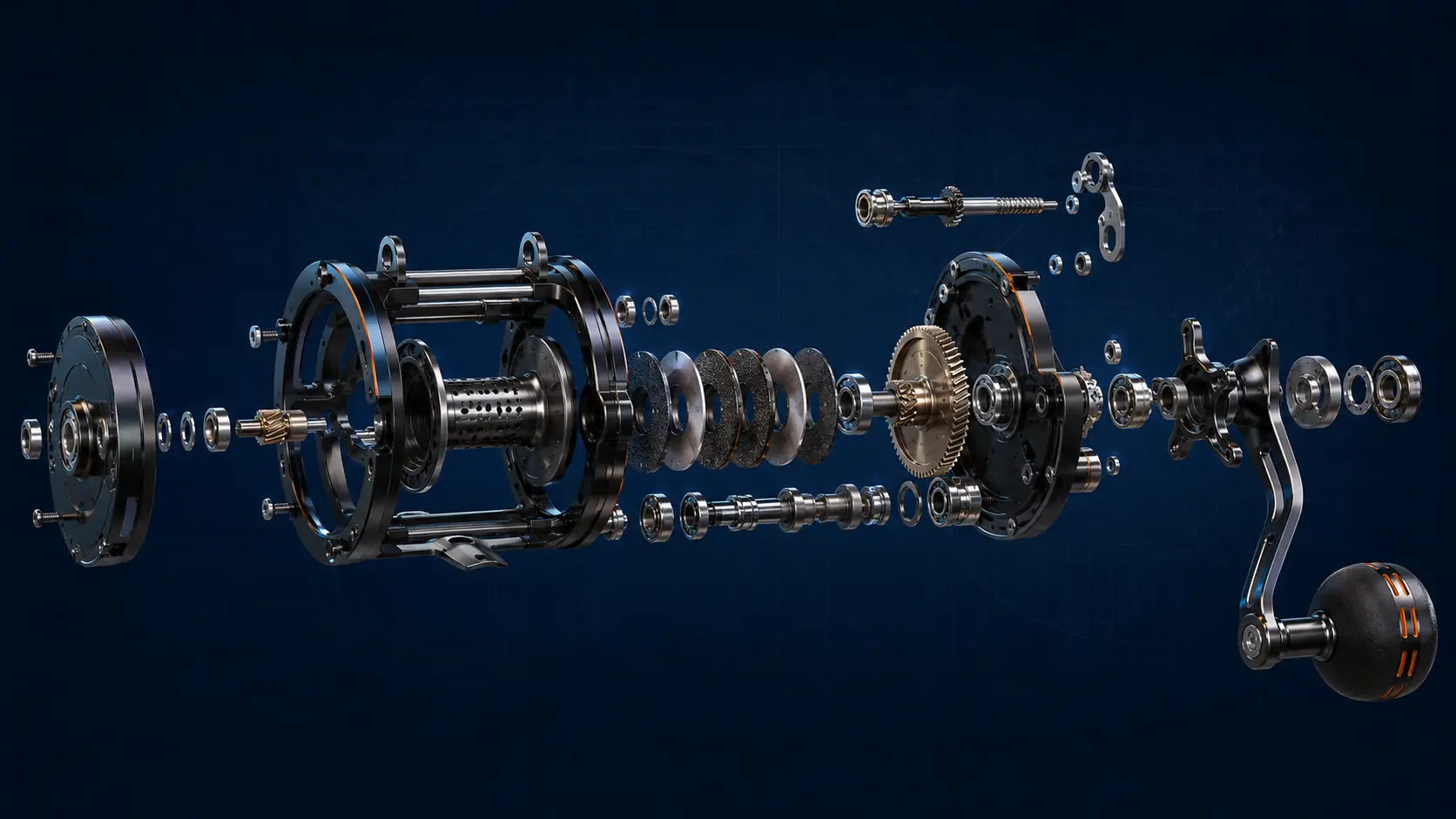
The frame, spool, main gear, pinion, drag washers, bearing seats and level-wind mechanism form one continuous load and transmission chain. The real CTQs are not isolated dimensions, but assembled coaxiality, center distance, gear mesh, drag stability and long-term corrosion resistance.
01 / RIGIDITY
Preserve the relationship between side plates, bearing bores and the spool axis under peak load
02 / SMOOTHNESS
Bearing bores, center distance, tooth geometry and shaft fits define feel and noise
03 / DRAG
Face quality, washer condition and spring preload shape a repeatable drag curve
04 / MARINE
Materials, finishes, sealing and dissimilar-metal pairing must work as one system
03 / PROVEN REEL PROGRAMS
30 / 50 / 60 CLASS REEL PROGRAMS
As spool diameter, frame span and handle torque change, bearing support, gear center distance, thin-wall distortion and assembly clearances all re-enter the tolerance chain. Each platform needs its own material, blank, datum and finishing strategy.
These are real dual-axis reel programs manufactured with Zhongde involvement, spanning compact, core mid-size and large-format platforms.
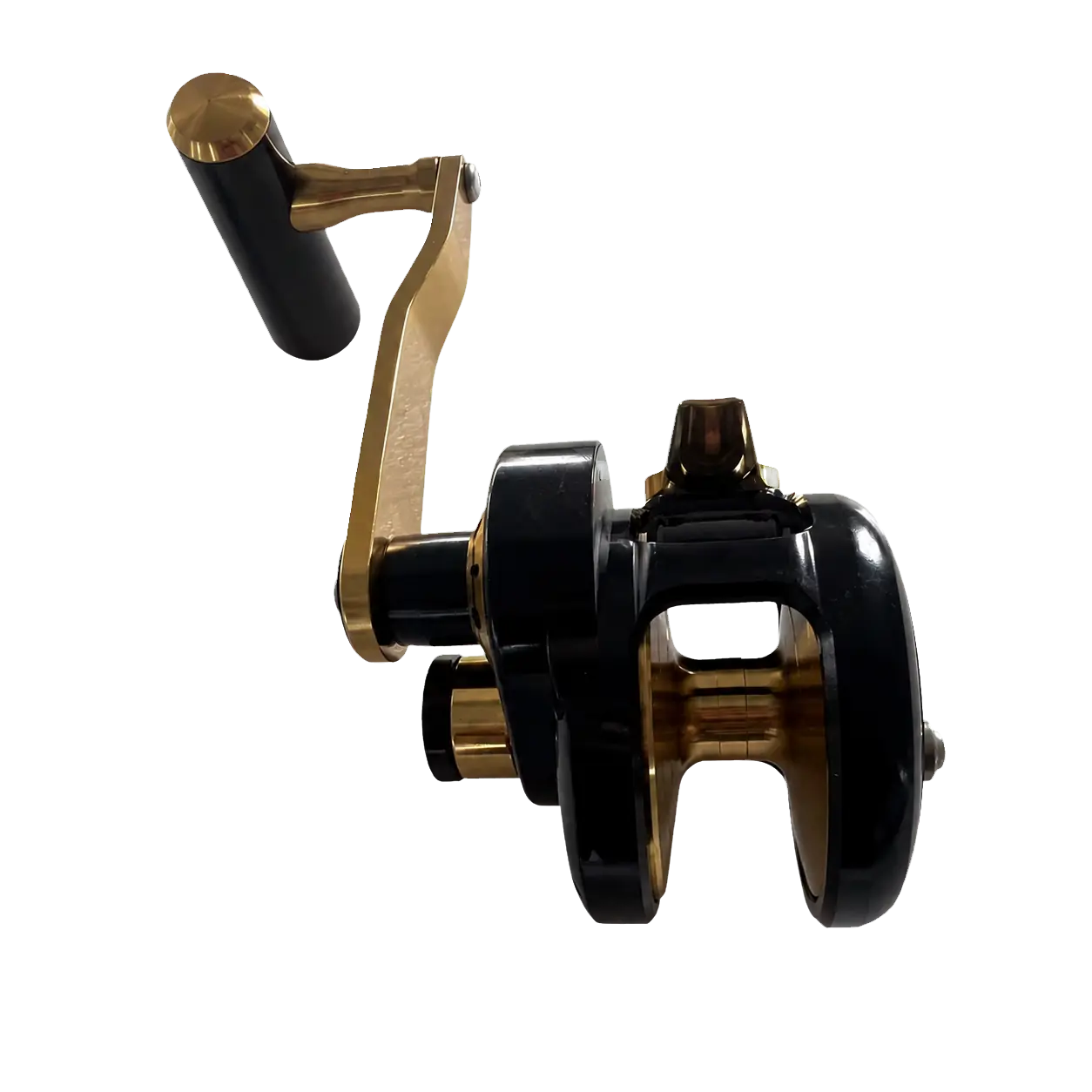
60 CLASS
A larger spool and frame span place greater demands on opposing bearing support, frame rigidity and machining-distortion control.
Frame rigidity · Shaft support · Distortion control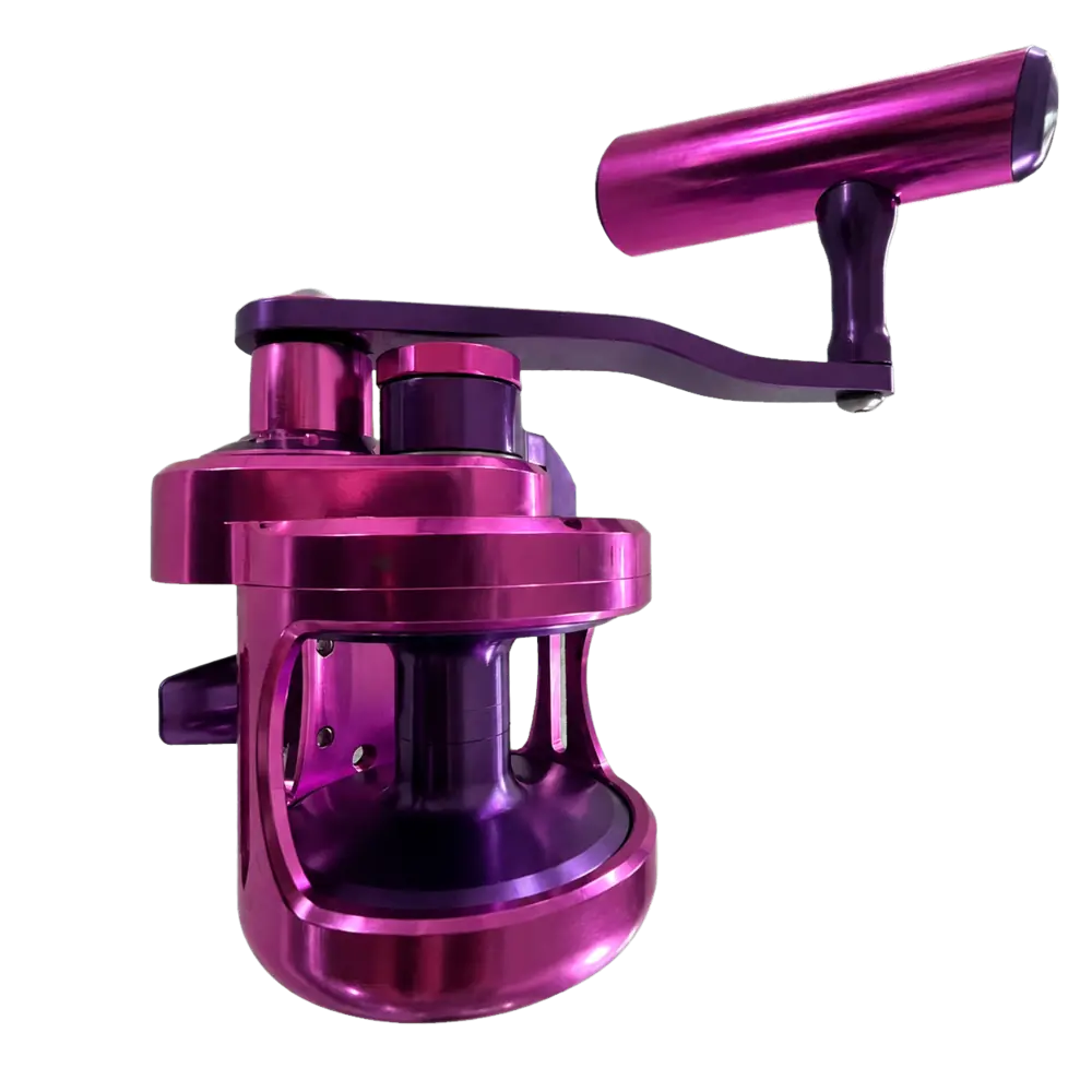
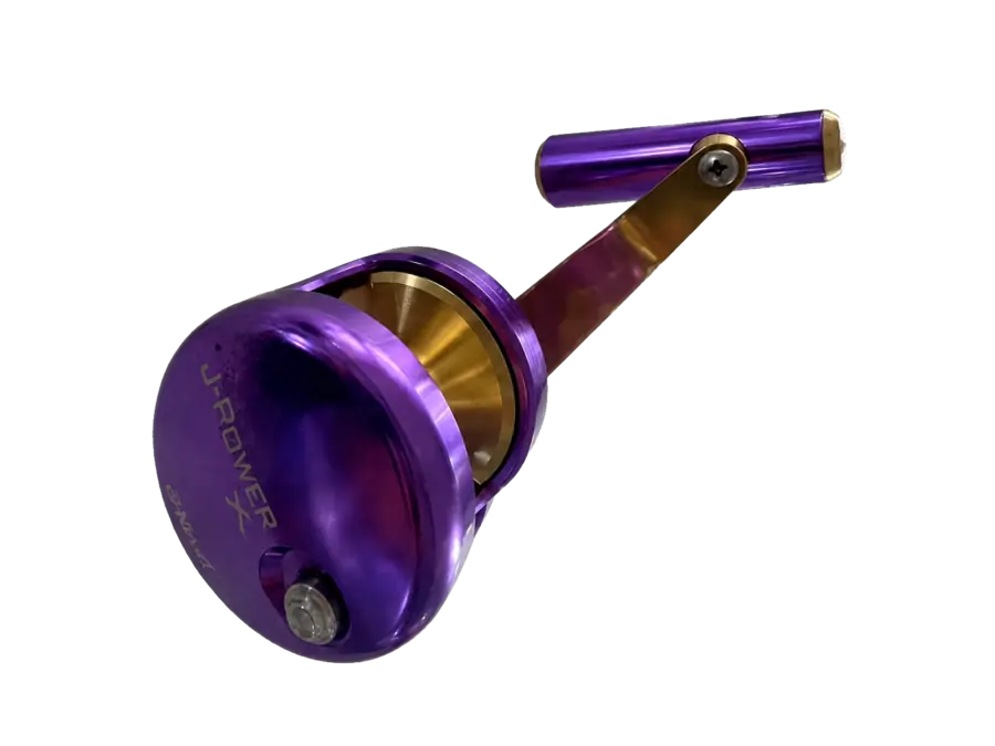
50 CLASS
Balance strength, mass and operating feel while controlling gear center distance, side-cover fit and anodized appearance consistency.
Strength-to-weight · Drive fit · Finish consistency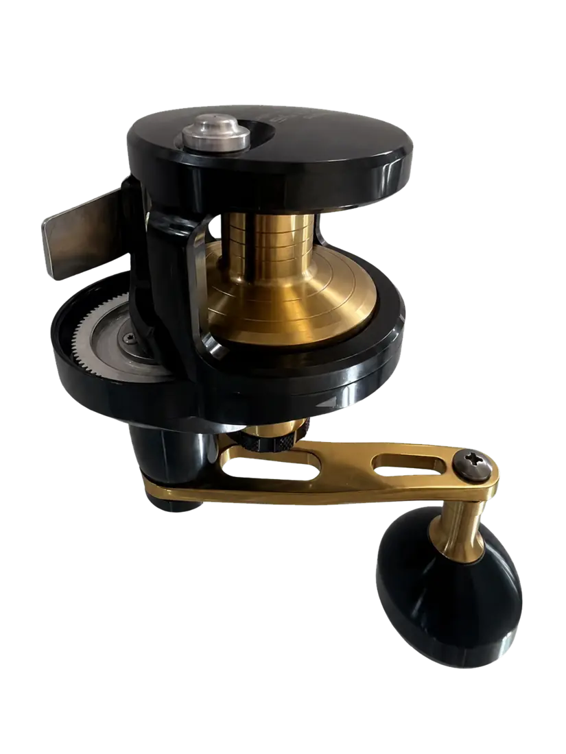
30 CLASS
As internal space tightens, thin-wall distortion, axial clearance and control-component fits become increasingly interdependent.
Thin-wall control · Assembly clearance · Control fit04 / CORE COMPONENT RANGE
STRUCTURE → ROTATION → DRIVE → CONTROL
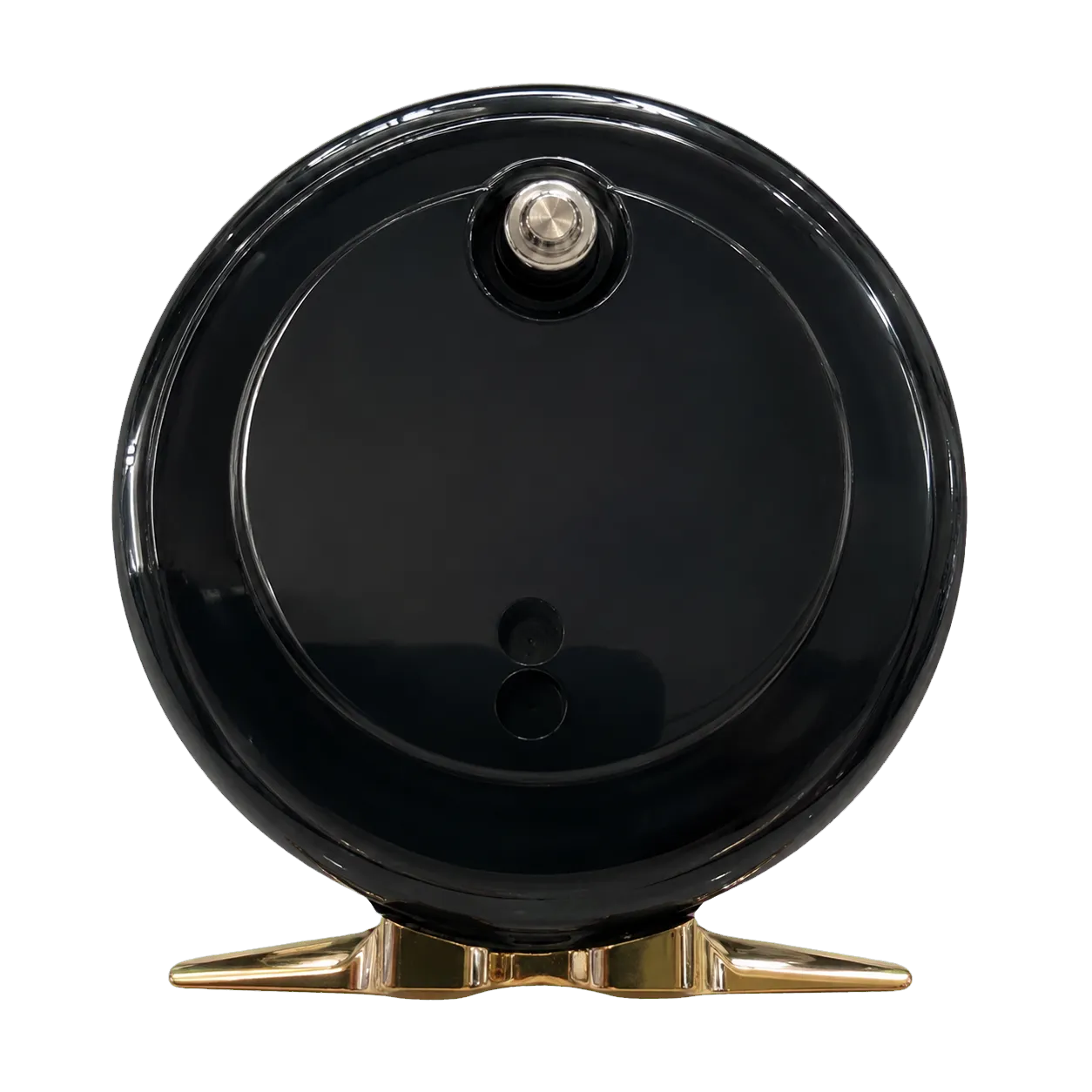
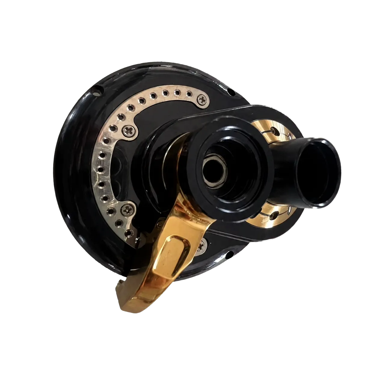
A dual-axis reel cannot be evaluated as isolated parts. Side covers establish shaft support, the spool carries geometry into rotation, the gear-and-shaft set transmits torque, and the handle converts internal precision into operating feel.
The components shown are manufactured and assembled parts that demonstrate the relationships among structural support, rotating axes, torque transmission and operator controls.
01 / SUPPORT & CONTROL
OPPOSING SIDE ASSEMBLIES
Both housings locate bearings or bushings, support adjustment mechanisms and define assembly interfaces. One side passing inspection does not establish the shaft line; the opposing locations must share a controlled datum strategy.
CTQs: bearing-seat position · perimeter fit · control travel · assembly datums
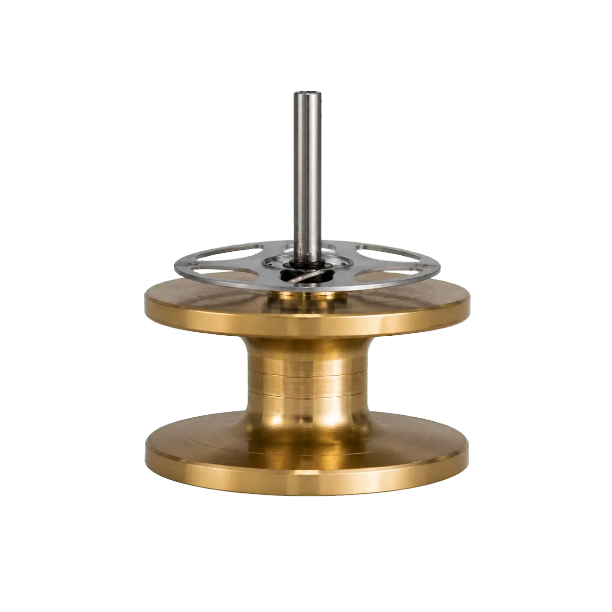
02 / SPOOL AXIS
LOW INERTIA ROTATION
Lightweight spool geometry, support at both ends and shaft-end fits jointly determine start-up inertia, runout and high-speed stability, directly affecting casting and retrieve behavior.
CTQs: coaxiality · radial/face runout · dynamic balance · shaft-end fit
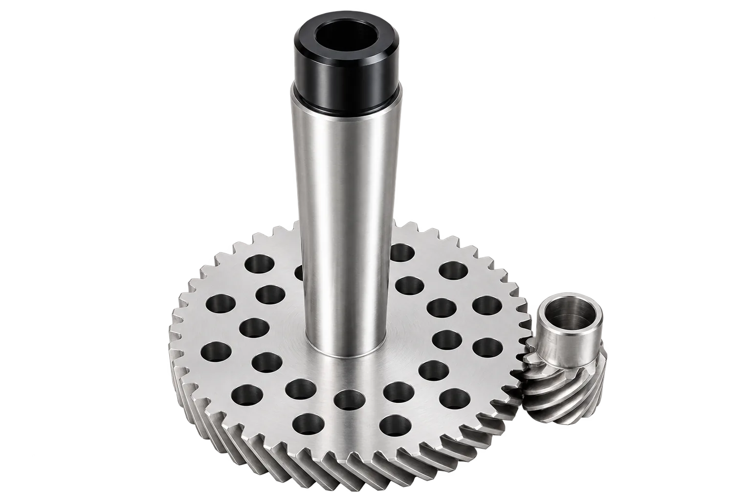
03 / DRIVE TRAIN
TORQUE TRANSMISSION
Tooth geometry, center distance and bore-to-shaft fits convert handle input into stable transmission. Gear parts must be evaluated together with side-cover bearing locations, housing datums and assembly preload.
CTQs: tooth mesh · center distance · bore/shaft fit · face condition
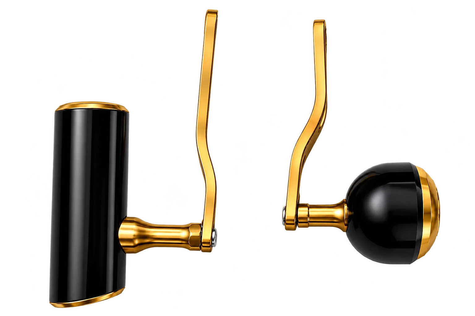
04 / HUMAN INPUT
TORQUE & OPERATING FEEL
Handle length amplifies input torque, while the mounting hole, grip shaft and rotational clearance define strength, backlash and feel. Exposed surfaces must also retain durability in marine use.
CTQs: hole position and profile · torque strength · rotational clearance · finish durability
PROCESSABLE PART MATRIX
Machinable parts are classified by functional system and connected to their primary CTQs so manufacturing requirements can be evaluated in the context of assembly relationships.
| System | Machinable parts | Primary CTQs |
|---|---|---|
| 01 Load-bearing structure | Main frame, left/right side plates, side covers, crossbars | Parallelism, bearing-bore position, assembly datums, structural deformation |
| 02 Spool axis system | Spool, spool shaft, bearing seats, bushings | Coaxiality, radial runout, face runout, axial clearance |
| 03 Drive system | Main gear, pinion gear, drive shaft, gear seats | Center distance, tooth mesh, bore/shaft fit, transmission noise |
| 04 Drag & clutch | Drag seat, star drag, clutch lever, pressure plates | Flatness, friction-face condition, travel and repeatability |
| 05 Control parts | Handle arms, knobs, adjustment knobs, end caps | Strength, profile, connection holes, operating feel |
| 06 Level-wind mechanism | Worm shaft, line guide, slider and related components | Straightness, pitch, running resistance, travel fit |
EXTENDED COMPONENT SCOPE
Next: material and process-route selection →
05 / PROCESS ROUTE SELECTION
MATERIAL → FORMING → MACHINING → FINISH
Materials and process routes are matched to part function, production volume, loading and appearance requirements, with die casting, forging, CNC machining and finishing evaluated as one continuous manufacturing plan.
ROUTE DECISION FACTORS
A production route combines material, blank process, machining datums, finishing and inspection requirements, all aligned during quotation and DFM review.
Ready for drawing review and manufacturing evaluation →
PROTOTYPE → PILOT → MASS PRODUCTION
Each phase confirms a different set of engineering outputs so part requirements, manufacturing conditions and quality controls can be progressively fixed.
01 / PROTOTYPE
Validate part geometry, material selection, assembly relationships and critical CTQs.
02 / PILOT PRODUCTION
Lock down machining datums, fixtures, tools, surface treatment and inspection methods.
03 / MASS PRODUCTION
Focus on CTQ process capability, lot stability and consistency across repeat production runs.
RFQ REQUIREMENTS
Complete project inputs help the engineering team confirm functional interfaces, manufacturing scope and quality requirements.
With these inputs, we can evaluate DFM, the process route, machining datums, surface treatment and the inspection plan.
Submit drawings and project requirementsPURCHASING FAQ
We can evaluate main frames, side plates and covers, spools and spool shafts, main and pinion gears, drive shafts, bearing seats, handle arms, knobs, drag and clutch structures, and level-wind components. Final scope is confirmed against the drawings and assembly requirements.
Typical options include die-cast aluminum, 6061 or 7075 aluminum, stainless steel, alloy steel, brass, POM and other engineering plastics. Final grade and condition depend on the drawing, load, corrosion resistance and finishing requirements.
Opposing bearing bores, bearing seats and shaft features are planned around shared assembly datums. In-process measurement and final assembly relationships are used to verify coaxiality, runout and clearance according to drawing CTQs and production volume.
Depending on the material and functional requirements, we can evaluate polishing, blasting, anodizing, coating, screen or pad printing, and laser marking. Color, coating build, masking and dimensional compensation are confirmed during DFM.
Yes. The engineering transition can cover prototype validation, pilot production and mass production, with CTQs, datums, fixtures, process conditions, finishing and inspection methods confirmed by phase.
Please provide the 2D drawing, 3D model, material, surface treatment, quantity or annual volume, critical CTQs and assembly requirements so DFM, process routing, datums and inspection can be evaluated.
Upload your drawings. Our engineering team will provide a manufacturing review and quotation within 24 hours.
