
In This Article
Direct Answer
The difference between 800G and 1.6T begins with aggregate bandwidth, but it does not end there. The engineering change runs through the complete interface system:
Switch ASIC and host SerDes
→ PCB channel and connector
→ module card-edge interface
→ DSP, drivers and optical engine
→ fiber interface
→ housing, heat spreader, TIM and system heatsink| Comparison | Common 800G Route | Main 1.6T Route | Manufacturing Impact |
|---|---|---|---|
| Aggregate bandwidth | 800 Gb/s | 1.6 Tb/s | Twice the port bandwidth and higher internal density |
| Host electrical interface | Commonly eight 100G-class PAM4 lanes | Commonly eight 200G-class PAM4 lanes; sixteen 100G-class lanes are another route | Greater sensitivity to card edge, connector, PCB and tolerance control |
| Common form factors | OSFP800, QSFP-DD800 | OSFP1600/OSFP224, QSFP-DD1600, OSFP-XD | A family name alone does not prove mechanical or electrical compatibility |
| Thermal design | Broad deployment and relatively mature cooling practice | More demanding total heat and hot-spot density in many designs | Thermal interface, stiffness, airflow and validation require a new review |
| Standards maturity | IEEE 802.3df-2024 is approved | As of August 2026, IEEE P802.3dj remains in late-stage standardization | Revision control and design freeze are more important |
| Production risk | Mature process and test ecosystem | Connector, optical engine, cooling and test ecosystems are still evolving | Pilot validation and change control cannot be skipped |
The IEEE 802.3df Task Force completed the 800 Gb/s Ethernet standard in 2024. The IEEE P802.3dj Task Force was still working through late-stage drafts and ballot activity for 1.6 Tb/s Ethernet in 2026. This means 800G has a more mature interoperability and production base, while a 1.6T program must identify the exact draft, MSA revision, host platform and module implementation.
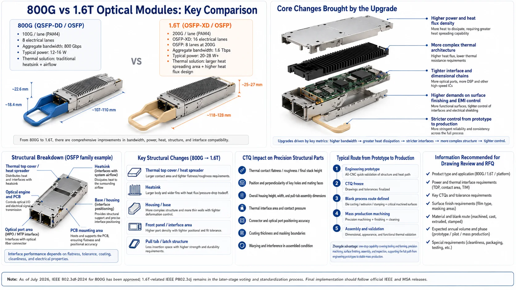
1. What Do 800G and 1.6T Actually Mean?
800G and 1.6T describe the aggregate data rate of a module or link. They do not mean that the module contains one electrical or optical lane operating at the full aggregate speed. High-speed pluggable modules divide the total bandwidth across parallel electrical lanes and one or more optical lanes.
1.1 A Common 800G Implementation
A common 800G host interface uses eight 100G-class PAM4 electrical lanes. The optical side can use different organizations depending on reach and product definition, including eight parallel optical lanes, four higher-rate optical lanes, wavelength multiplexing, or two independent sub-interfaces. Electrical lane count and optical lane count should never be assumed to be identical.
1.2 Two Main Host-Interface Paths to 1.6T
Path A: Eight 200G-class electrical lanes
8 × 200G-class electrical lanes ≈ 1.6T aggregate bandwidthThis path is associated with OSFP1600, OSFP224 and QSFP-DD1600 directions. It keeps the electrical lane count at eight, but each channel operates at a higher signaling rate and has a more demanding insertion-loss, crosstalk and equalization budget.
Path B: Sixteen 100G-class electrical lanes
16 × 100G-class electrical lanes ≈ 1.6T aggregate bandwidthOSFP-XD increases the number of electrical lanes to reach a higher aggregate rate. Its connector, card edge and mechanical system differ from standard OSFP, so the two are not cross-compatible.
The OSFP MSA states that standard OSFP has eight high-speed electrical lanes supporting 8×50G, 8×100G and 8×200G operation. OSFP-XD has sixteen lanes and a separate mechanical and electrical specification. The QSFP-DD MSA similarly defines QSFP-DD, QSFP-DD800 and QSFP-DD1600 around eight 50G-, 100G- and 200G-class lanes.
2. How Do the Standards and Product States Differ?
2.1 800G Is in the Post-Standard, Scaled-Deployment Phase
IEEE Std 802.3df-2024 defines relevant MAC parameters and physical layers for 800 Gb/s Ethernet. 800G OSFP and QSFP-DD products are already widely used in AI clusters and data-center switching. For a manufacturing supplier, this usually means:
- more mature reference designs for modules, cages, connectors and cooling;
- broader access to inspection fixtures, insertion tests and thermal test methods;
- deeper supply-chain experience with housings, thermal lids, pull tabs and finishes;
- fewer unknowns, although customer-specific drawing control remains essential.
2.2 1.6T Is Productizing While Its Ecosystem Is Still Converging
As of August 2026, IEEE P802.3dj had reached late draft and Standards Association ballot activity, but not every 1.6T implementation should be treated as equivalent. Product families and samples already exist. For example, InnoLight’s AI and data-center portfolio lists both 800G and 1.6T products. However, vendors can use different DSPs, silicon-photonics or EML architectures, fiber interfaces and thermal solutions.
A drawing marked only as “1.6T OSFP” is therefore not enough for a reliable quotation. The supplier must confirm:
- OSFP1600, OSFP224, QSFP-DD1600, OSFP-XD or another definition;
- eight 200G-class or sixteen 100G-class host lanes;
- DR8, 2×DR4, FR4, 2×FR4 or another optical architecture;
- required backward compatibility with 800G ports or modules;
- integrated heatsink, flat-top module or riding-heatsink configuration;
- the governing MSA and customer-specification revision.
3. How Do OSFP, QSFP-DD and OSFP-XD Differ?
| Form Factor | High-Speed Electrical Lanes | 800G Path | 1.6T Path | Manufacturing Review Focus |
|---|---|---|---|---|
| OSFP / OSFP800 / OSFP1600 | 8 | 8×100G | 8×200G | Integrated or external cooling, card edge, forward stop, cage and connector tolerances |
| QSFP-DD800 / QSFP-DD1600 | 8 | 8×100G | 8×200G | Signal, thermal and structural balance inside a tighter envelope |
| OSFP-XD | 16 | Higher-density combinations | 16×100G for 1.6T | Separate connector and card edge; not cross-compatible with OSFP |
3.1 The Same Form-Factor Family Does Not Guarantee Direct Replacement
OSFP MSA Rev 5.1 provides dedicated card-edge, connector and mechanical-tolerance definitions for OSFP1600. Although OSFP1600 belongs to the OSFP family, an older port cannot be assumed to operate reliably at 1.6T. Mechanical insertion, power, signal integrity and worst-case tolerance compatibility must be reviewed separately.
3.2 A Smaller Part Is Not Necessarily Easier to Manufacture
QSFP-DD offers high front-panel density, but the compact envelope limits heatsink height, housing-wall thickness, internal optical space and pull-tab space. One structural assembly may need to provide:
- heat spreading and contact with an external heatsink;
- EMI shielding and grounding;
- PCB and optical-engine location;
- insertion guidance, forward stop and latching;
- fiber-interface protection;
- labeling, serial identification and traceability.
A smaller component can have less tolerance margin even when its absolute dimensions are reduced.
4. Does 1.6T Always Use Twice the Power of 800G?
Power cannot be scaled directly from bandwidth.
A 1.6T module can use a newer process node, DSP, silicon-photonics platform and driver technology, reducing energy per bit. At the same time, higher bandwidth and component density can increase total module power, local hot-spot temperature or heat flux per unit area. The thermal design must combine:
Total power
+ hot-spot location and area
+ internal spreading path
+ housing and spreader materials
+ TIM conductivity and compressed thickness
+ thermal-surface flatness and roughness
+ system heatsink and airflow
+ inlet temperature and altitude
= junction and case-temperature margin
4.1 Higher Bandwidth Can Redistribute Heat Sources
The transition from 800G to 1.6T can increase or relocate heat from:
- DSP and SerDes functions;
- lasers, drivers, TIAs and optical engines;
- power-conversion and management devices;
- connector and power-contact temperature rise;
- front-to-rear module temperature gradients.
A thermal lid therefore cannot be controlled by one average height alone. The relative position of multiple local contact pads, thin walls and assembly datums may become a new CTQ.
4.2 Inspect Thermal Surfaces in the Defined Final Condition
Surface treatment, assembly preload, thin-wall distortion and measurement clamping can all change the thermal interface. Acceptance must define whether the part is measured:
- after machining;
- after surface treatment;
- in the free state;
- in the assembled state;
- at a specified temperature and support condition.
A surface that is flat inside a CNC fixture may not maintain uniform contact after the module is inserted into a cage and loaded through a TIM.
5. What Changes in the Structural Parts?
5.1 The Housing and Lid Become Multi-Function Interfaces
A high-speed transceiver housing often connects several systems at once:
External heatsink / RHS
↕
thermal lid, heat spreader or module housing
↕
DSP, optical engine, laser and internal TIM
↕
PCB, card edge and host connector
↕
cage, front panel, latch and fiber interface
The 1.6T challenge is not one tighter dimension but stronger coupling between interfaces. Changing thermal-pad height can affect total module height and insertion. Increasing housing stiffness can consume optical-engine space. Coating thickness can change grounding and assembly dimensions around the card edge.
5.2 Pull Tab, Latch and Forward Stop Are Functional Dimensions
Full insertion depends on the module forward stop, cage stop, card-edge location, connector seating plane and latch mechanism. A shift in any one of these can cause:
- insufficient electrical engagement;
- abnormal insertion force;
- incomplete latching;
- front-panel position variation;
- misalignment of the external heatsink contact area.
This is a functional tolerance chain, not a single housing-length dimension.
5.3 EMI and Grounding Affect Surface Treatment
As signaling rates rise, continuous housing ground, cage-finger contact, coating masks and contact resistance become more important. Anodizing can improve corrosion resistance and cosmetic consistency, but its insulating film cannot cover every grounding region. Electroless nickel or exposed conductive areas also need defined boundaries, thickness and final inspection methods.
6. Which Characteristics Are True CTQs?
A CTQ is not simply the dimension with the smallest printed tolerance. It is a characteristic whose loss of control can affect bandwidth, thermal performance, insertion, assembly, EMI or reliability.
| CTQ Category | Typical Characteristics | Failure Effect | Suggested Validation |
|---|---|---|---|
| Thermal interface | Flatness, roughness, final height, local steps, surface condition | Excess TIM thickness, partial contact, hot-spot rise | CMM/flatness, roughness, pressure print, thermal test |
| Electrical interface | Forward stop to card edge, card-edge thickness, connector-related location | Insufficient engagement, signal failure, insertion problem | Functional gauge, CMM, actual connector insertion |
| Optical engine and PCB datums | Mounting-plane parallelism, hole location, locating pins, profile | Optical-coupling shift, solder stress, assembly interference | CMM, assembly validation, optical functional test |
| Module envelope | Height, width, critical profile, pull-tab motion space | Cage or adjacent-port interference | MSA gauge and actual cage validation |
| EMI and grounding | Conductive contact area, coating thickness, mask boundary, continuity | Reduced shielding and higher contact resistance | Thickness, boundary inspection, continuity and EMI validation |
| Structural stability | Thin-wall thickness, free-state warp, assembled distortion | Thermal mismatch, optical stress, insertion drag | Free-state and assembled-state comparison |
| Cleanliness and surface | Burrs, particles, adhesive residue, scratches, optical-port protection | Contamination, short circuit, interface damage | Microscopy, cleanliness and packaging validation |
How Do Ordinary Dimensions Differ from CTQs?
A label-pocket length can have a small tolerance but limited functional impact. A wider-tolerance forward-stop location may control connector engagement and heatsink alignment. Priority should be based on:
Functional impact
× failure severity
× process sensitivity
× detection difficulty
= control priority
7. What Does This Mean for Structural-Part Sourcing and Zhongde’s Machining Scope?
When a platform moves from 800G to 1.6T, Zhongde does not manufacture the transmission protocol. The relevant opportunity is the way changes in devices, power density and interface architecture are transferred into mechanical parts and production controls. Five changes matter most:
More sensitive thermal interfaces
+ More strongly coupled functional datums
+ Less margin for thin-wall distortion
+ More complex surface-treatment boundaries
+ Stricter prototype-to-production validation
7.1 Which Parts Can Become Practical Machining Projects?
| Typical part | Common manufacturing route | Critical machining and validation work | Scope Zhongde can support |
|---|---|---|---|
| Aluminum upper housing or thermal lid | Full CNC for prototypes; die-cast or extruded stock plus CNC for volume | Thermal contact surface, final height, thin-wall warpage, holes and envelope | Stock-route review, precision CNC, surface treatment and CMM inspection |
| Precision lower housing or base | Plate CNC, die casting plus CNC, or a combined route | Datums between the PCB, optical engine, connector and housing | Functional-surface machining, tolerance-chain control and assembled-condition checks |
| Aluminum or copper heat spreader | CNC from plate or bar | Flatness, roughness, thickness, local steps and assembly contact | Aluminum and copper machining, thermal-interface finishing, cleaning and dimensional inspection |
| External heat sink or mounting plate | Aluminum extrusion plus local CNC | Mounting plane, hole position, critical profile, fin protection and post-anodize dimensions | Secondary extrusion machining, deburring, anodizing and final inspection |
| Pull tab, latch and support feature | Stamping, CNC or combined process | Insertion, forward stop, locking, motion clearance and burr control | Machining of critical interfaces, assembly and functional-dimension checks |
| Prototype and production gauges | Aluminum, steel or engineering plastic | MSA envelope, assembly simulation, key positions and repeatable measurement | Fixtures, gauges and assembly-assist tooling |
Not every part should remain a fully machined component. The sourcing route should be selected from prototype quantity, annual volume, CTQs, tooling investment and design maturity. The value is not forcing one process onto every design; it is preserving the same functional datum scheme across stock preparation, precision machining, surface treatment, assembly and inspection.
7.2 Prototype and Production Routes Should Not Be Identical by Default
Full CNC machining is useful while the design is still changing because it supports fast revisions and functional validation. Once the design and volume stabilize, a fully machined route may no longer provide the best cost or takt time. A practical transition is:
CNC prototype from solid stock
→ Validate envelope, assembly and thermal interfaces
→ Freeze CTQs and tolerance chains
→ Evaluate die-cast, extruded or other formed stock
→ CNC-machine critical functional surfaces
→ Apply surface treatment and local masking
→ Verify assembly, CMM results and functional gauges
→ Run pilot production and confirm process capability
This path matches Zhongde’s integrated capabilities in tooling, forming, precision machining, polishing, surface treatment, assembly and inspection. The purpose is not simply to place every process with one supplier. It is to reduce datum loss between suppliers, missed coating-thickness compensation, unclear responsibility for abnormalities and failure to transfer prototype know-how into repeatable production.
7.3 What Can Zhongde Support, and Where Is the Boundary?
Zhongde can support metal housings, precision bases, heat spreaders, heat-sink mounting structures, finish machining of formed stock, surface treatment, local masking, cleaning, subassembly, CMM inspection and CTQ control from prototype through production.
Zhongde should not be presented as a DSP or optical-chip designer. Its scope does not include EML or silicon-photonics chip fabrication, core fiber-coupling processes, high-speed electrical design, IEEE or MSA certification, or complete optoelectronic performance qualification of the finished transceiver. A clear manufacturing boundary keeps drawing review, quotation scope and quality responsibility aligned.
8. Why Can Production Fail After Prototypes Pass?
A 1.6T prototype is often built at low speed by experienced engineers using repeated compensation and full inspection. Production introduces variation from:
- residual-stress changes between extrusion, plate or die-cast material lots;
- heat buildup and tool wear during continuous deep-pocket and thin-wall machining;
- datum transfer across multiple setups;
- anodizing, electroless nickel and masking lots changing final height;
- lot differences in pull tabs, springs, TIMs and fasteners;
- CMM program, clamping and operator differences;
- cleaning, packaging and transport damage to thermal or optical interfaces.
The most dangerous condition is not one clearly nonconforming part. It is a set of parts that are each near their individual limits and consume the full assembly tolerance when combined.
Production Release Needs Four Types of Evidence
- Product evidence: CTQs and functional tolerance chains are frozen;
- Process evidence: machines, fixtures, tools and finishing routes are repeatable;
- Measurement evidence: the inspection system can distinguish real variation;
- Functional evidence: thermal, insertion, assembly, EMI and reliability validation has passed.
9. What Should the Supplier Confirm During DFM?
9.1 Stock and Machining Route
- whether the design is better suited to extrusion, machined plate, die casting or a stamped assembly;
- whether the thermal contact should be finished after major material removal and stabilization;
- whether roughing, stress relief, semi-finishing and final finishing should be separated;
- whether thin walls, deep slots and fins can be machined at a controlled production rate;
- whether one datum strategy can continue through machining, finishing, assembly and inspection.
9.2 Surface Treatment and Masking
- which regions require conductivity, insulation, corrosion resistance or cosmetic consistency;
- whether the thermal contact can accept a coating;
- how card edge, grounding pads, threads, precision bores and assembly datums are masked;
- how coating thickness enters the final tolerance chain;
- whether flatness, roughness and critical dimensions are rechecked after finishing.
9.3 Inspection and Functional Validation
- whether CMM inspection represents the free state or an assembled simulation;
- whether actual cage, connector and RHS gauges are required;
- whether thermal contact is verified through pressure print, interface resistance or system temperature;
- how insertion force, latch, release and life are validated;
- who owns EMI, grounding-continuity and cleanliness validation.
10. What Inputs Are Required for a 1.6T Structural-Part RFQ?
| RFQ Input | Required Detail | Risk If Missing |
|---|---|---|
| Product definition | OSFP1600, OSFP224, QSFP-DD1600, OSFP-XD or custom | Wrong interface and gauges |
| Governing revision | MSA, IEEE draft or customer specification | Drawing and platform mismatch |
| 2D and 3D data | Datums, GD&T, material, final condition, critical profile | No reliable process or inspection plan |
| Host interface | Eight 200G-class or sixteen 100G-class lanes, connector and cage model | Card-edge and forward-stop relationship unknown |
| Thermal input | Total power, hot-spot map, case target, TIM, load and airflow | Material, flatness and cooling route cannot be selected |
| Optical architecture | DR8, 2×DR4, FR4, 2×FR4 or another type | Optical-port and internal assembly boundary unknown |
| Surface treatment | Finish type, thickness, conductive regions, mask boundary and cosmetics | Dimension, grounding and thermal-interface failure |
| Validation | CMM, roughness, insertion, thermal, EMI, reliability and cleanliness | Quotation omits necessary validation cost |
| Quantity and phase | Prototype, EVT/DVT/PVT, annual volume and takt | Wrong stock and process route |
| Change rules | Material, machine, fixture, finishing line and program changes | Prototype learning does not transfer to stable production |
11. How Should an 800G-to-1.6T Upgrade Be Reviewed?
When a customer has a mature 800G platform, the 1.6T upgrade should begin with an interface delta review rather than a CNC-program edit:
Standard and form factor
→ host electrical interface and connector
→ optical architecture
→ power and hot spots
→ envelope and airflow
→ functional datums and tolerance chains
→ material, machining and finishing
→ inspection and reliability
For Zhongde, the valuable capability is not making a broad claim that it can machine a “1.6T housing.” It is reviewing the customer drawings, power map, assembly condition and validation boundary, then translating those inputs into measurable and traceable CTQs. A prototype can move toward stable production only when the thermal interface, connector position, optical-engine datum, insertion mechanism and surface treatment are managed in one functional tolerance system.
Frequently Asked Questions
Is a 1.6T optical transceiver simply an 800G module running at twice the speed?
No. Aggregate bandwidth increases from 800 Gb/s to 1.6 Tb/s, but the host electrical interface, SerDes rate, DSP and optical-engine architecture, connector loss, thermal path, mechanical tolerances and test methods may all change. The project must be reviewed around its actual eight-lane 200G, sixteen-lane 100G or other architecture rather than multiplying the 800G parameters by two.
Does every 1.6T optical transceiver use OSFP?
No. OSFP1600 or OSFP224 is a common route, while QSFP-DD1600 also supports 1.6T through eight 200G-class electrical lanes. OSFP-XD can reach 1.6T through sixteen 100G-class lanes. Selection depends on switch-port density, connector and PCB capability, cooling space, power, serviceability and ecosystem compatibility.
Does a 1.6T module always consume twice the power of an 800G module?
No. Total power depends on the DSP, optical architecture, reach, lasers, drivers, package and process node. Energy per bit may improve, while higher bandwidth can still increase total module heat or local heat flux. Thermal design must use the actual power map, airflow, inlet temperature, TIM and allowable case temperature instead of scaling power directly with data rate.
What information is required for a 1.6T structural-part RFQ?
Provide the module form factor and MSA revision, 2D and 3D drawings, host electrical interface, optical architecture, total power and hot-spot map, thermal contact and TIM requirements, airflow, cage and connector models, functional datums, surface treatment, assembly condition, CTQs, prototype and production quantities, and thermal, insertion, EMI and reliability validation requirements.
