
In This Article
Direct Answer
The manufacturing route for an AI server cold plate should not be selected only by asking which option “cools better.” The real decision factors are channel complexity, cover and sealing design, thermal contact surface accuracy, allowable pressure drop, operating pressure, cleanliness, and production volume.
For relatively simple structures and early-stage validation, CNC-machined channels with a sealed cover plate are usually the most flexible option. When the internal structure is more complex, the cooling area is larger, or production volume is defined, a multi-piece brazed structure may be more appropriate. Microchannels should be evaluated when heat flux is high and conventional channels can no longer meet the temperature-rise target.
These three routes are not low-, medium-, and high-grade versions of the same product. Each serves a different design envelope and production condition.
| Project condition | Manufacturing route to evaluate first |
|---|---|
| Rapid prototyping and a design that may still change | CNC-machined channels with cover plate sealing |
| Complex channels, larger area, and defined production volume | Multi-piece structure followed by brazing |
| High heat flux and limited heat-transfer area | Microchannel structure |
1. Why the Manufacturing Route Must Be Defined Early
A cold plate must transfer heat from CPUs, GPUs, power devices, or other heat sources into the coolant while maintaining reliable channels, ports, and sealing features over long-term operation. It is therefore not simply a machined exterior part, but a functional assembly shaped by thermal, fluid, structural, and manufacturing requirements.
The manufacturing route affects whether the channels can be machined, whether the interior can be cleaned, how the cover is sealed, whether the thermal contact surface can remain flat, and whether leak, pressure, and flow tests can be performed effectively. If the geometry is frozen before manufacturability is reviewed, common problems include inaccessible channels, excessively small internal radii, impractical deep-cavity proportions, insufficient wall thickness near ports, and distortion after sealing.
Four different decision levels should also be separated. Microchannels describe a channel architecture; CNC describes a machining method; brazing, friction-stir welding, and O-ring sealing describe joining or closure methods; ports, hoses, quick disconnects, and mounting brackets belong to system integration. These decisions interact, but they are not equivalent alternatives on one axis.
| Decision level | What must be defined | Typical options |
|---|---|---|
| Channel architecture | How coolant is distributed through the heat-source region | Serpentine, parallel, distributed, finned, multilayer, microchannel |
| Part and machining concept | How the channels and structural parts are formed | CNC machining, one-piece base, layered construction, separately machined parts |
| Joining and sealing | How the base, channel layer, and cover become a closed structure | Brazing, welding, friction-stir welding, mechanical sealing |
| System integration | How the cold plate connects to the processor, tubing, and chassis | Port orientation, quick disconnects, tubing, mounting bracket, leak detection |
At minimum, the following three boundaries should be reviewed together during the design stage.
| Design boundary | Questions to resolve | Manufacturing impact |
|---|---|---|
| Thermal and fluid boundary | Heat flux, flow rate, allowable pressure drop, temperature-rise target | Determines channel cross-section, path length, branch count, and whether microchannels are needed |
| Structural and sealing boundary | Cover plate, ports, seal groove, mounting holes, thermal contact surface | Determines part segmentation, sealing route, machining sequence, and final machining scope |
| Reliability boundary | Operating pressure, proof pressure, leakage rate, thermal cycling, service life | Determines material, wall thickness, joining method, and validation plan |
The manufacturing route should therefore be decided before the thermal design, structural design, and production drawing are fully frozen—not treated as an afterthought.
2. CNC-Machined Channels with Cover Plate Sealing
In this route, channels or cavities are machined into a base plate and then closed with a cover plate. The design may use a single serpentine path, parallel channels, island-type flow distribution, or multiple variants within the same outer geometry for comparison of temperature rise, pressure drop, and flow distribution.
The main value of CNC machining is development speed and design flexibility. Prototype tooling investment is limited, and channel width, depth, distribution features, or port location can often be adjusted through program and fixture changes. Channel depth, locating surfaces, mounting holes, and thermal contact surfaces can also be inspected at intermediate stages.
Its limitations are equally clear. More complex channels increase machining time; narrow or deep channels are limited by cutter diameter, overhang, and rigidity; and internal corners are constrained by tool radius. After channel machining, the cover plate sealing method, internal cleanliness, and distortion of thin plates still require separate control.
| Evaluation item | Typical performance of the CNC route |
|---|---|
| Development speed | Fast; suitable for prototypes and engineering validation |
| Design changes | Flexible through program and fixture revisions |
| Internal complexity | Moderate; limited by tool access and cutter radius |
| Main risks | Machining time, burrs and residue, cover sealing, and thin-plate distortion |
| Best-fit stage | Prototypes, low-to-medium volume, and designs that may still change |
Once the product is stable and machining time or material removal becomes excessive, brazing or another production-oriented architecture should be re-evaluated.
3. Brazed Cold Plate Structures
Microchannels are not produced by one process alone. The route should be selected according to channel regularity, blind-channel requirements, channel count, material, prototype quantity, and production scale.
The modular assembly illustrates a multi-cold-plate system. The cutaway shows that performance depends on channel organization, heat-source contact, and coolant distribution—not simply on making every passage narrower.
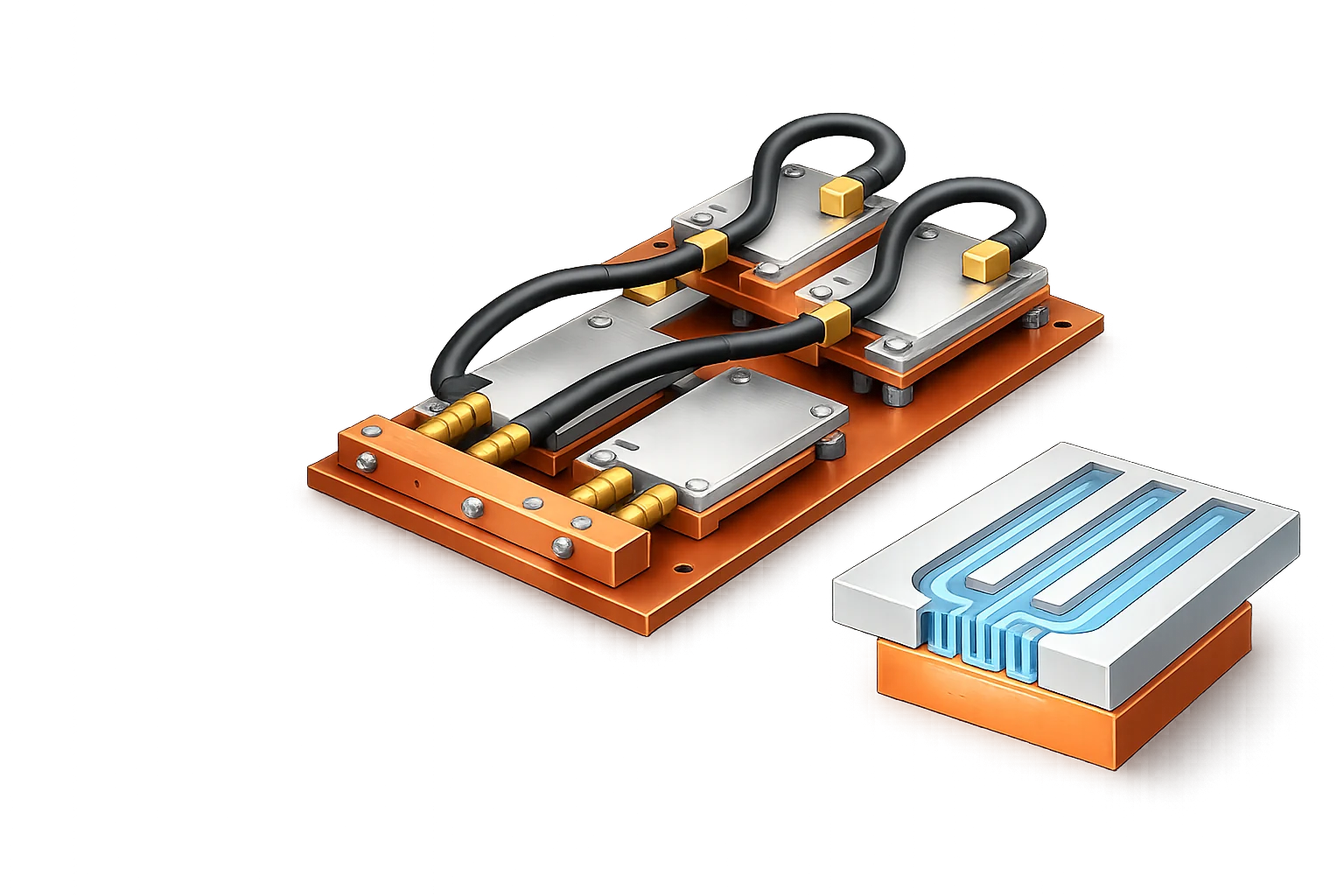
A brazed cold plate is usually built from a base plate, channel layer, fins, separators, or cover plate. The individual components are machined first, then cleaned, located, assembled, and brazed to form a sealed internal flow path.
This route can create internal structures that are difficult to machine directly from one piece. It is also suitable for larger cold plates and products that require internal fins, turbulence features, or multilayer channels. Once the structure, fixturing, and process window are stable, brazing can offer greater potential for production optimization.
The challenge is not merely whether the parts can be joined. Stable joint clearance, filler-metal flow, assembly location, thermal distortion, and internal blockage all have to be controlled. A good exterior appearance does not guarantee complete internal bonding, so post-braze machining, leak testing, pressure testing, flow testing, and—when required—thermal validation must be part of the process plan.
| Main risk | Possible result | Key control method |
|---|---|---|
| Unstable joint clearance | Local lack of bonding or excessive filler metal | Control part flatness, joint gap, and assembly location |
| Uneven filler-metal distribution | Channel blockage or local leakage | Optimize filler quantity, placement, and thermal cycle |
| Distortion after heating | Shift of thermal surface, ports, or mounting holes | Use constraint fixtures and reserve post-braze machining |
| Insufficient cleanliness | Oxidation, contamination, or reduced joint quality | Establish pre-braze cleaning, drying, and contamination control |
| Hidden internal defects | Acceptable appearance but abnormal leakage or flow | Combine leak, proof-pressure, and flow verification |
Brazed structures are most suitable when the internal geometry is complex, the cooling area is large, the design is relatively stable, and production volume is clearly defined.
4. Microchannel Cold Plates
The purpose of microchannels is to increase the effective heat-transfer area between the coolant and the metal while shortening the heat-conduction path. However, as the channel size decreases, pressure drop, manufacturing difficulty, cleaning difficulty, and blockage risk all increase.
A microchannel design therefore cannot be defined by thermal simulation alone. Channel width, depth, count, wall thickness, surface condition, and inlet/outlet distribution must be evaluated together with pump capability, filtration, coolant properties, and manufacturing tolerances.
| Design factor | Potential benefit | Additional risk |
|---|---|---|
| Narrower channels | Greater heat-transfer area | Higher machining, cleaning, and blockage risk |
| Deeper channels | Greater flow area | Lower tool rigidity and dimensional stability |
| More channels | Larger cooling region | More difficult flow balancing |
| Higher velocity | Potentially improved heat transfer | Higher pressure drop and pump load |
| Thinner walls | Potentially lower thermal resistance | Lower strength, proof pressure, and distortion margin |
| Different surface condition | Changes boundary-layer and heat-transfer behavior | May increase pressure drop and contaminant adhesion |
Microchannels are most appropriate when power density is high, the heat source is concentrated, conventional channels cannot meet the temperature target, and the system can accept higher pressure drop with strong filtration and cleanliness control.
5. How to Choose Among the Three Routes
The following table can be used as an early project-screening reference.
| Comparison item | CNC-machined channels | Brazed structure | Microchannel structure |
|---|---|---|---|
| Prototype speed | Fast | Medium | Relatively slow |
| Design flexibility | High | Medium | Lower |
| Internal complexity | Medium | High | High |
| Process-control difficulty | Medium | Relatively high | High |
| Sealing risk | Depends on cover design | Must be tightly controlled | Must be tightly controlled |
| Cleaning difficulty | Medium | Medium to high | High |
| Pressure-drop risk | Medium | Depends on channel design | Higher |
| Production optimization potential | Medium | High | Depends on process maturity |
| Best-fit stage | Prototype and low-to-medium volume | Stable design and production | High heat-flux applications |
Hybrid routes are also common. A project may use a CNC prototype to validate geometry and thermal performance, then move to a brazed production structure after the design stabilizes. Another design may combine conventional main channels with a local microchannel region and restore thermal contact surfaces and mounting datums through post-braze machining.
The best route is not the most complex one. It is the route that can consistently satisfy thermal performance, reliability, inspection, and production-cost requirements.
6. Engineering Inputs Required Before Process Selection
The manufacturing route cannot be selected from a 2D drawing alone. The supplier also needs the thermal target, flow boundary, mechanical mounting interface, sealing concept, system integration requirements, reliability requirements, and production conditions. Without these inputs, the proposal depends on assumptions and may later require channel redesign, sealing changes, connector relocation, or revised test standards.
| Input category | Core information to confirm | Manufacturing impact |
|---|---|---|
| Thermal and fluid conditions | Coolant, target flow rate, allowable pressure drop, heat load, inlet/outlet temperature | Determines channel cross-section, path length, branch count, and need for microchannels |
| Thermal contact and mounting interface | Contact area, flatness, roughness, total height, mounting load, keep-out zones, installation space | Determines material-stress control, fixturing, finishing sequence, post-join machining, and inspection method |
| Structure and sealing | 2D drawing, 3D model, outer dimensions, mounting holes, datums, cover plate, seal groove, joining method | Determines part segmentation, machining sequence, cover design, joining route, and final finishing scope |
| System integration and wetted materials | Port position and orientation, tubing routing, quick-disconnect specification, coolant, wetted metals, seal materials, leak-detection arrangement | Affects port machining, material combination, surface treatment, galvanic-corrosion risk, and assembly testing |
| Pressure and reliability | Operating pressure, pressure spikes, proof pressure, leakage rate, thermal cycling, shock, vibration, expected life | Determines material, wall thickness, joining method, brazing parameters, and leak-test method |
| Prototype and production conditions | Prototype quantity, annual volume, takt time, cost boundary, traceability, inspection ratio | Determines whether CNC, brazing, or a dedicated production route is more suitable |
Not every value needs to be frozen at the beginning, but confirmed parameters and assumptions must be clearly separated. Open items should be identified during quotation and process review so that production risk is not discovered only after prototype validation.
7. Manufacturing Risks and the Validation Matrix
Cold plate failures are often not caused by one isolated dimensional error, but by interactions among machining, sealing, cleanliness, system interfaces, and validation. The following four issues are among the most common.
| Risk | Main cause | Possible result | Control focus |
|---|---|---|---|
| Loss of thermal contact surface flatness | Material stress, asymmetric stock removal, fixturing, sealing heat input | Higher contact resistance and local distortion after assembly | Control material condition, machining sequence, fixture constraint, and final inspection condition |
| Burrs and residue inside channels | Inadequate deburring, cleaning, or drying | Blockage of pumps, valves, filters, or fine channels | Establish deburring, cleaning, drying, and secondary-contamination controls |
| Unstable sealing geometry | Mismatch of groove size, compression, roughness, screw distribution | Assembly leakage or reduced long-term reliability | Evaluate groove geometry, cover rigidity, port load, and assembly sequence together |
| Leak test only, without flow verification | Incomplete validation plan | Local blockage or uneven distribution may remain undetected | Combine leak, proof-pressure, flow, pressure-drop, and required thermal testing |
Each manufacturing route should be linked to a complete validation matrix. Passing a leak test shows only that no leak was detected under the specified condition; it does not prove that the channels are unobstructed, that pressure drop fits the system limit, or that the thermal contact surface and overall thermal performance meet the requirement.
| Validation category | Main checks | Purpose |
|---|---|---|
| Dimensional and assembly | Envelope, height, flatness, roughness, port orientation, installation interference | Confirm correct installation and stable thermal contact |
| Internal quality | Channel dimensions, blockage, contamination, weld or joint defects | Detect internal abnormalities that cannot be found by appearance |
| Sealing and proof pressure | Gas leak, hydrostatic pressure, pressure hold, leakage at ports and joints | Verify sealing reliability of channels and connections |
| Fluid performance | Flow rate, pressure drop, branch distribution | Identify blockage, local resistance, or uneven flow distribution |
| Thermal performance | Temperature rise or thermal resistance at multiple flow rates | Confirm that the design meets the processor temperature target |
| Environmental and material reliability | Thermal cycling, vibration, shock, wetted-material compatibility, corrosion risk | Verify long-term reliability after operation, transport, and assembly |
Cold plate performance should not be judged from one temperature-rise value. Engineering validation should record the device reference temperature, coolant inlet temperature, heat load, and pressure drop at multiple flow rates, then calculate thermal resistance:
R = (Tc − TL) / Q
Here, Tc is the device case or specified reference temperature, TL is the coolant inlet temperature, and Q is the applied heat load. Testing at multiple flow rates helps determine whether an apparent improvement comes from effective heat transfer or simply from a higher pump load.
The key is to move verification into the manufacturing process rather than relying only on final inspection.
8. Re-Evaluating the Route from Prototype to Production
Prototype development focuses on proving geometry and thermal performance. Production focuses on takt time, yield, fixture life, tool life, process capability, inspection efficiency, and traceability. A successful CNC prototype therefore does not mean the same process should automatically be retained for production.
| Stage | Core objective | Items to confirm |
|---|---|---|
| Concept and prototype | Validate geometry and basic thermal performance | Channel concept, port position, sealing method, preliminary pressure drop |
| Engineering validation | Confirm reliability and critical dimensions | Flatness, leakage, proof pressure, flow, cleanliness, assembly repeatability |
| Production preparation | Establish a stable process window | Fixtures, tooling, takt time, CTQs, inspection frequency, abnormal-response process |
| Stable production | Control batch consistency and cost | Process capability, traceability, sampling plan, change control, continuous improvement |
When volume, structure, or reliability requirements change, the blank, part segmentation, sealing method, and inspection plan should be re-evaluated instead of simply copying the prototype route.
9. What to Provide When Requesting a Quotation
A customer does not need to separate every requirement into a long checklist, but the following five information groups should be clear.
| Information category | Recommended content |
|---|---|
| Controlled design data | 2D drawing, 3D model, revision, and key change notes |
| Material and structure | Material grade and temper, channel design, ports, sealing method, surface treatment |
| Performance and reliability | Operating pressure, proof pressure, allowable leakage, flow, pressure drop, coolant |
| Quality and validation | Thermal contact surface, cleanliness, inspection report, traceability, validation standard |
| Project conditions | Prototype quantity, expected volume, target lead time, and production plan |
If the design is still at an early stage, a preliminary model and key performance targets are enough to begin a manufacturability review. Confirming the process boundaries early is usually more effective than waiting until every drawing detail is frozen.
Frequently Asked Questions
Does every cold plate require vacuum brazing?
No. The need for vacuum brazing depends on the flow-channel structure, sealing area, material combination, production volume, thermal performance, and reliability requirements. For simpler structures or prototype validation, machined channels combined with another cover-sealing method may also be evaluated.
Is a CNC-machined cold plate suitable for volume production?
Yes, but machining time, tool life, number of channels, fixturing, sealing design, and inspection takt time must all be evaluated. For stable designs with defined volume, dedicated fixtures, standardized tooling, and process optimization can significantly improve production efficiency.
Do smaller microchannels always provide better cooling?
No. Smaller channels can increase heat-transfer area, but they can also increase pressure drop, machining difficulty, and blockage risk. Channel dimensions must be designed together with flow rate, coolant, pump capability, cleanliness, and manufacturing tolerances.
What information is required for a cold plate quotation?
Recommended inputs include controlled 2D drawings, 3D models, material and temper, channel structure, port specifications, operating pressure, proof-pressure requirements, allowable leakage rate, thermal contact surface requirements, surface treatment, cleanliness, expected volume, and validation standards.
