
In This Article
Direct Answer
A liquid cold plate is the functional component closest to the heat source in a direct-to-chip cooling system. One side interfaces with a CPU, GPU or power device, while coolant flows through internal channels on the other side to carry heat into the server cooling loop.
It is not simply a metal plate with a water groove. A production-ready cold plate must simultaneously provide:
- Stable contact with the chip or thermal interface material;
- Effective coolant coverage of major heat-load regions;
- Flow and pressure drop within system limits;
- Leak-tight covers, ports and joined regions;
- Controlled burrs, chips, braze material and cleaning residues;
- Compatible metals, coolant, seals and surface treatments;
- A manufacturing process that can reproduce prototype performance in volume production.
The heat path is:
Chip → Thermal Interface Material → Cold Plate Base → Internal Heat-Transfer Structure → Coolant
The OCP liquid cooling cold plate requirements evaluate thermal performance, pressure drop, leakage, proof pressure, materials, reliability and interfaces together. ASHRAE also describes cold plates as components with specific temperature, flow, pressure-drop, material-compatibility and cleanliness boundaries. A cold plate should therefore not be accepted on external dimensions alone.
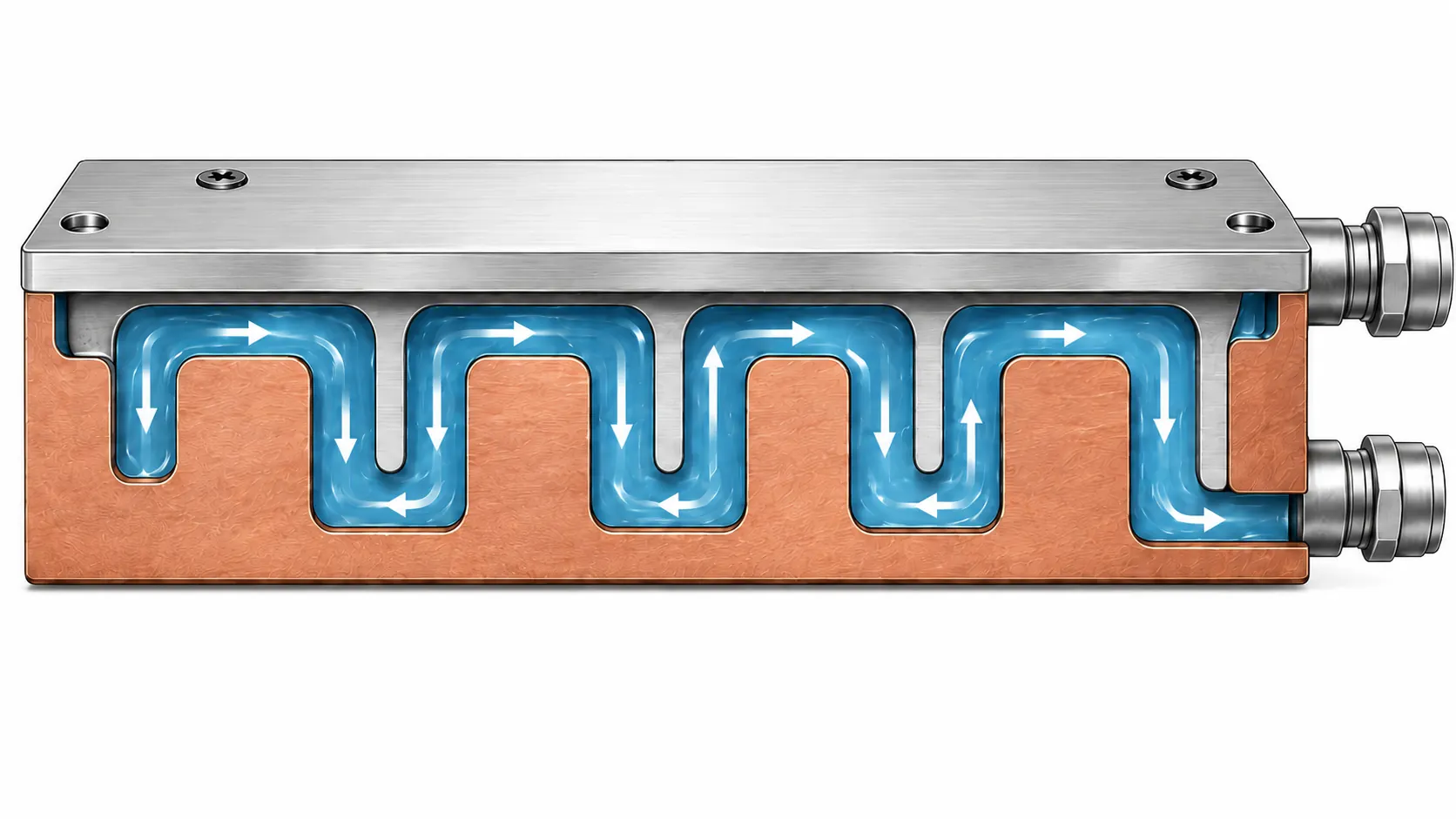
Main illustration of the liquid cold plate, highlighting the base plate, top cover, serpentine channel and inlet/outlet port structure.
1. What Structures Make Up a Liquid Cold Plate?
A typical cold plate includes six functional regions.
| Functional Region | Main Function | Typical Manufacturing Risk |
|---|---|---|
| Thermal contact base | Receives heat from the chip | Flatness, roughness and thickness variation |
| Internal channels | Distribute coolant and transfer heat | Dimensional error, burrs, blockage and pressure-drop variation |
| Cover or sealing layer | Forms the enclosed flow path | Incomplete joining, distortion and leakage |
| Inlet and outlet ports | Connect tubing or manifolds | Orientation, threads and sealing surfaces |
| Mounting and locating features | Control position and load | Hole position, datums and total-height variation |
| Sealed or joined regions | Maintain long-term containment | Seal groove, weld, braze or clamping-load defects |
These regions interact. A thinner base may reduce conduction distance but increase distortion and pressure risk. A port too close to a channel can create insufficient wall thickness. A flexible cover may deflect under proof pressure or mounting load.
2. How Does a Cold Plate Remove Heat?
Cold plate performance depends on several thermal resistances:
- Contact between the chip and thermal interface material;
- Contact between the TIM and cold plate surface;
- Conduction through the cold plate base;
- Conduction from the base into channel walls;
- Convection from the metal wall into the coolant;
- Heat transport out of the cold plate by the coolant.
Higher material conductivity alone does not solve every problem. A thick base increases conduction distance, while an excessively thin base may deform. Higher flow can improve heat transfer but also raises pressure drop and pumping demand. A very flat contact surface cannot compensate for poor internal flow distribution.
Design and manufacturing must balance:
| Objective | Potential Conflict |
|---|---|
| Lower thermal resistance | May require thinner bases and denser channels |
| Lower pressure drop | May require wider and shorter channels |
| Higher strength | May require thicker walls and covers |
| Lower mass | May reduce structural stiffness |
| Lower cost | May limit materials, layers and machining time |
| Higher reliability | Requires more cleaning, testing and validation |
3. Common Flow-Channel Structures
Serpentine Channels
A serpentine channel carries coolant along one continuous route through the heat-load area.
It offers a clear flow path and concentrated flow, but a long route can increase pressure drop and create larger inlet-to-outlet temperature differences.
Parallel Channels
Parallel channels divide coolant among multiple branches.
They can shorten individual paths, but the inlet distributor, outlet collector and branch resistance must be controlled carefully. Dimensional variation or burrs can cause maldistribution.
Pin-Fin and Turbulence Features
Pin fins, islands and turbulence structures can increase heat-transfer area and modify local flow.
Manufacturing reviews should consider tool access, root radii, spacing, deburring and cleaning. Dense features can raise pressure drop and contamination risk.
Microchannels
Microchannels provide more heat-transfer area within a limited footprint and can support high heat-flux zones.
They are not automatically the best option. Microchannels are more sensitive to manufacturing tolerance, particles, filtration, cleaning, coolant and pressure drop. Detailed manufacturability should link to the existing microchannel cold plate article.
Multilayer Channels
Multilayer structures can create crossed channels, distribution layers and localized heat-transfer regions, but they increase part count, alignment, joining, inspection and cleaning complexity.
| Channel Type | Main Advantage | Main Risk |
|---|---|---|
| Serpentine | Simple path and concentrated flow | Long path and higher pressure drop |
| Parallel | Short branches and broad coverage | Flow imbalance |
| Pin-fin/turbulence | Increased heat-transfer area | Machining, burr and cleaning complexity |
| Microchannel | High heat-flux capability | Pressure drop, blockage and tolerance sensitivity |
| Multilayer | Flexible routing and integration | Joining and internal-validation complexity |
4. Selecting Aluminum, Copper or a Copper-Aluminum Structure
Aluminum Alloys
Aluminum alloys provide low density and good machinability for larger cold plates, lightweight structures and volume CNC production. Grades such as 6061 and 6063 may be considered depending on strength, thermal, brazing, welding and surface-treatment requirements.
Copper
Copper provides higher thermal conductivity and can be useful where the heat source is concentrated or base dimensions are restricted. Its density, material cost, tool wear, machining cycle and surface protection must also be considered.
Copper-Aluminum Combinations
A copper insert can be placed near the heat source while aluminum is used for the body or cover. This can balance thermal spreading, weight and cost, but introduces joining, galvanic-corrosion, thermal-expansion and long-term reliability concerns.
The OCP guidelines for water-based heat-transfer fluids emphasize compatibility among coolant, wetted materials and operating conditions. Material selection should therefore be made for the entire wetted loop, not for the cold plate in isolation.
| Evaluation | Aluminum | Copper | Copper-Aluminum |
|---|---|---|---|
| Thermal conductivity | Good | Higher | Higher near selected zones |
| Weight | Low | High | Medium |
| CNC productivity | Generally good | Usually lower | Depends on part split |
| Joining | Alloy and process dependent | Structure dependent | More difficult |
| Corrosion control | Coolant dependent | Coolant dependent | Higher galvanic concern |
| Cost | Generally controlled | Higher | Medium to high |
| Typical use | Large, lightweight, volume parts | Concentrated heat loads | Performance-weight compromise |
5. Why the Base, Channel Walls and Cover Cannot Simply Be Made Thinner
Important thickness relationships include:
- Base thickness between the chip contact surface and channel;
- Rib thickness between adjacent channels;
- Minimum wall from channels to the outside edge;
- Distance from channels to threaded or mounting holes;
- Cover thickness;
- Finishing allowance after joining.
Reducing base thickness can shorten the heat path, but it can also increase:
- Material-stress distortion;
- Clamping deformation;
- Joining distortion;
- Bending under mounting load;
- Base or cover deflection under pressure;
- Risk of insufficient finishing allowance.
Thickness should be selected with thermal simulation, structural analysis, material condition, machining sequence, joining and final assembly state.
6. Manufacturing CTQs for the Thermal Contact Surface
Flatness
Flatness affects TIM compression and chip loading. A plate that is acceptable in the free state may distort after it is installed.
The inspection condition should state:
- Free or mounted condition;
- Before or after joining;
- Before or after surface treatment;
- Temperature condition;
- Datum and support method.
Roughness
Surface roughness affects the real contact condition with the TIM. The target should match TIM type, thickness and mounting pressure rather than simply pursuing a mirror finish.
Position and Total Height
The contact surface, mounting holes, locating features and fluid ports form one dimensional chain. Total-height or hole-position error can change mounting load or transfer stress into the package.
| CTQ | Required Definition |
|---|---|
| Flatness | Inspection state, datums, temperature and process stage |
| Roughness | Measurement direction, sampling zone and TIM requirement |
| Contact-surface height | Reference datum and tolerance |
| Mounting-hole position | Datum system and assembly stack |
| Surface treatment | Masking and coating-thickness influence |
| Surface protection | Scratch prevention, packaging and handling |
7. Flow-Channel and Pressure-Drop CTQs
Channel dimensions are not only drawing characteristics; they are system-performance parameters.
Important controls include:
- Channel width and depth;
- Branch cross-section;
- Distributor and collector geometry;
- Turns, radii and local restrictions;
- Pin-fin or microfeature spacing;
- Channel-surface condition and burrs;
- Inlet and outlet orientation;
- Internal blockage and residue.
Two parts with identical external dimensions can have different pressure drop because of channel depth, burrs or joining-material distribution.
Dimensional and functional testing should therefore be combined.
| Inspection | Potential Finding |
|---|---|
| Channel dimensional inspection | Width, depth and local-geometry errors |
| Visual or internal inspection | Burrs, blockage and joining defects |
| Flow test | Overall flow capability |
| Pressure-drop test | Restriction, blockage and geometry variation |
| Multi-branch flow test | Maldistribution |
| Cleanliness test | Particle and residue risk |
8. How the Cover Forms a Sealed Flow Path
Cold plates may use:
- Mechanical seals and bolted clamping;
- Vacuum brazing;
- Friction stir welding;
- Laser welding or another welding method;
- Diffusion bonding;
- Other process-specific joining methods.
The selected route affects:
- Part separation;
- Joint geometry;
- Heat input and distortion;
- Internal cleanliness;
- Post-join machining;
- Nondestructive inspection;
- Leak and proof-pressure testing;
- Production cycle and cost.
This article defines the selection boundaries. Detailed comparison of CNC, brazing and microchannel routes should link to the existing cold plate manufacturing-process article.
9. Ports, Seals and Material Compatibility
Cold plate ports may use threaded fittings, pressed fittings, welded tubes, quick disconnects or direct manifold connections.
Typical port CTQs include:
- Position and orientation;
- Thread specification and effective depth;
- Sealing-surface geometry and roughness;
- Connector-seat wall thickness;
- Tool clearance;
- Tube bend radius;
- Assembly load;
- Supply-return error prevention.
Seal materials must be compatible with the coolant, temperature, pressure, life and cleaning fluids. Metals, seals, coolant and surface treatments cannot be qualified independently and then combined without review.
10. Why Internal Cleanliness Is a Functional CTQ
Burrs, chips, abrasive particles, cleaning residues, braze material and corrosion products can migrate into:
- Microchannels;
- Valves;
- Quick disconnects;
- Filters;
- Pumps;
- Sensors;
- Other server branches.
Internal cleanliness is therefore a flow and reliability requirement, not a cosmetic requirement.
A controlled process may include:
- Deburring after channel machining;
- Cleaning and drying before joining;
- Residue control after joining;
- Final flushing;
- Particle or residue verification;
- Prevention of secondary contamination;
- Port capping;
- Clean packaging.
The cleaning method must be compatible with channel geometry and materials.
11. How Should a Liquid Cold Plate Be Validated?
The OCP cold plate development and qualification white paper treats performance, reliability and test methods as a combined development process. Manufacturing acceptance should not depend on a single test.
| Validation | Main Content | Purpose |
|---|---|---|
| Dimensional | Form, hole position, flatness, roughness and ports | Assembly and thermal contact |
| Internal quality | Channels, blockage, joining and cleanliness | Detect hidden defects |
| Leak | Specified pressure and leak rate | Verify containment |
| Proof pressure | Specified pressure and hold time | Confirm structural margin |
| Flow and pressure drop | Multiple flow points | Verify system matching |
| Thermal | Temperature, load, flow and pressure drop | Verify heat transfer |
| Thermal cycling | Dimensions and leakage after cycling | Evaluate joints and seals |
| Vibration and shock | Transport and operating conditions | Evaluate interfaces and structure |
| Material compatibility | Coolant, metals, seals and coatings | Evaluate corrosion and contamination |
A passed leak test cannot replace flow, pressure-drop or thermal validation. A good appearance cannot prove internal joining quality.
12. Which CTQs Must Be Frozen for Production?
Prototype builds can rely on higher inspection ratios and manual adjustment. Production requires controlled, repeatable conditions.
| Stage | Main Task |
|---|---|
| Concept prototype | Validate channels, ports and basic thermal performance |
| Engineering validation | Confirm flatness, pressure drop, sealing, cleanliness and assembly |
| Production preparation | Freeze material, tooling, joining, cleaning and inspection |
| Stable production | Control capability, traceability, sampling, deviations and changes |
Production control should define:
- Characteristics requiring 100% inspection;
- Batch or sampling inspections;
- Flow and pressure-drop test conditions;
- Leak and proof-pressure media, pressure, time and acceptance;
- Cleanliness limits and sampling method;
- Surface-treatment and masking requirements;
- Revision, lot and test-data traceability;
- Requalification triggers for supplier, material or process changes.
13. Information Required for a Cold Plate RFQ
| Category | Recommended Input |
|---|---|
| Controlled design | 2D drawings, 3D model, revision and change records |
| Thermal | Chip load, target temperature and contact area |
| Fluid | Coolant, flow, pressure drop and temperature range |
| Pressure | Operating, peak, proof pressure and leak rate |
| Materials | Base, cover, wetted metals and seal materials |
| Channels | Geometry, dimensions, branches, residue and cleanliness |
| Ports | Threads, fittings, orientation and service clearance |
| Surface | Flatness, roughness, coating and masking |
| Validation | Dimensional, leak, proof, flow, pressure-drop and thermal tests |
| Project | Prototype quantity, forecast volume, lead time and ramp plan |
When the design is not fully frozen, separate confirmed parameters from assumptions. Early manufacturing input on channel geometry, part split, joining and testing can reduce later redesign.
Frequently Asked Questions
How is a liquid cold plate different from an air-cooled heat sink?
An air-cooled heat sink transfers heat into air through fins, while a liquid cold plate transfers heat into coolant flowing through internal channels. Cold plates therefore require combined control of the thermal contact surface, channels, pressure drop, sealing, cleanliness and fluid connections.
Is aluminum or copper better for a liquid cold plate?
There is no universal answer. Copper provides higher thermal conductivity but has different weight, cost and machining conditions. Aluminum is lightweight and generally easier to machine for larger or higher-volume parts. The final choice must also consider coolant compatibility, corrosion, joining, surface treatment, geometry and cost.
Do smaller cold plate channels always improve cooling?
No. Smaller channels may increase heat-transfer area, but they can also increase pressure drop, blockage risk, manufacturing difficulty and cleaning difficulty. Channel size must be selected with the heat load, flow rate, pump capability, coolant, filtration and manufacturing tolerances.
Is leak testing alone enough after cold plate manufacturing?
No. A leak test only shows that no leakage was detected under the specified test conditions. It does not prove that channels are free from blockage, that flow and pressure drop meet requirements, or that the thermal contact surface and thermal performance are acceptable. Dimensional, cleanliness, proof-pressure, flow, pressure-drop and thermal validation may also be required.
