
In This Article
Direct answer
Sealing, flatness, and pressure verification form one connected quality chain rather than three independent inspection items.
Sealing structure
Defines leakage paths, compression, assembly window, and long-term robustness.
Contact flatness
Controls thermal-interface uniformity and may interact with the sealing boundary.
Leak testing
Detects leakage above a defined threshold but does not prove channel openness.
Proof pressure
Checks structural, fitting, and joint stability above normal operating pressure.
A useful specification must define the medium, pressure, stabilization time, measurement time, temperature, fixture condition, instrument resolution, and acceptance limit.
“Zero leakage,” “pressure held,” and “flatness passed” are not complete engineering requirements by themselves.
1. Separate four different meanings of “pass”
| Item | Main question answered | What it cannot replace |
|---|---|---|
| Flatness | Will the thermal surface contact uniformly? | Does not prove sealing |
| Leak test | Is leakage below the defined limit? | Does not prove channel openness |
| Proof pressure | Can the structure withstand the defined pressure? | Does not prove long-term cycling life |
| Flow/pressure drop | Are channels open and flow distribution acceptable? | Does not prove external leak tightness |
A plate can pass a pneumatic leak test while debris blocks part of the internal channel. Pressure may remain stable even though cooling performance has already deteriorated.
2. Sealing and flatness must be managed together
A cold plate usually contains at least two critical planes: the thermal contact surface facing the device and the sealing plane used by the cover, gasket, O-ring, braze, or weld. They may use different datums, yet assembly can make them interact.
A single final flatness value cannot reveal whether distortion originated from base machining, the seal groove, cover preload, brazing, welding, or final mounting bolts.
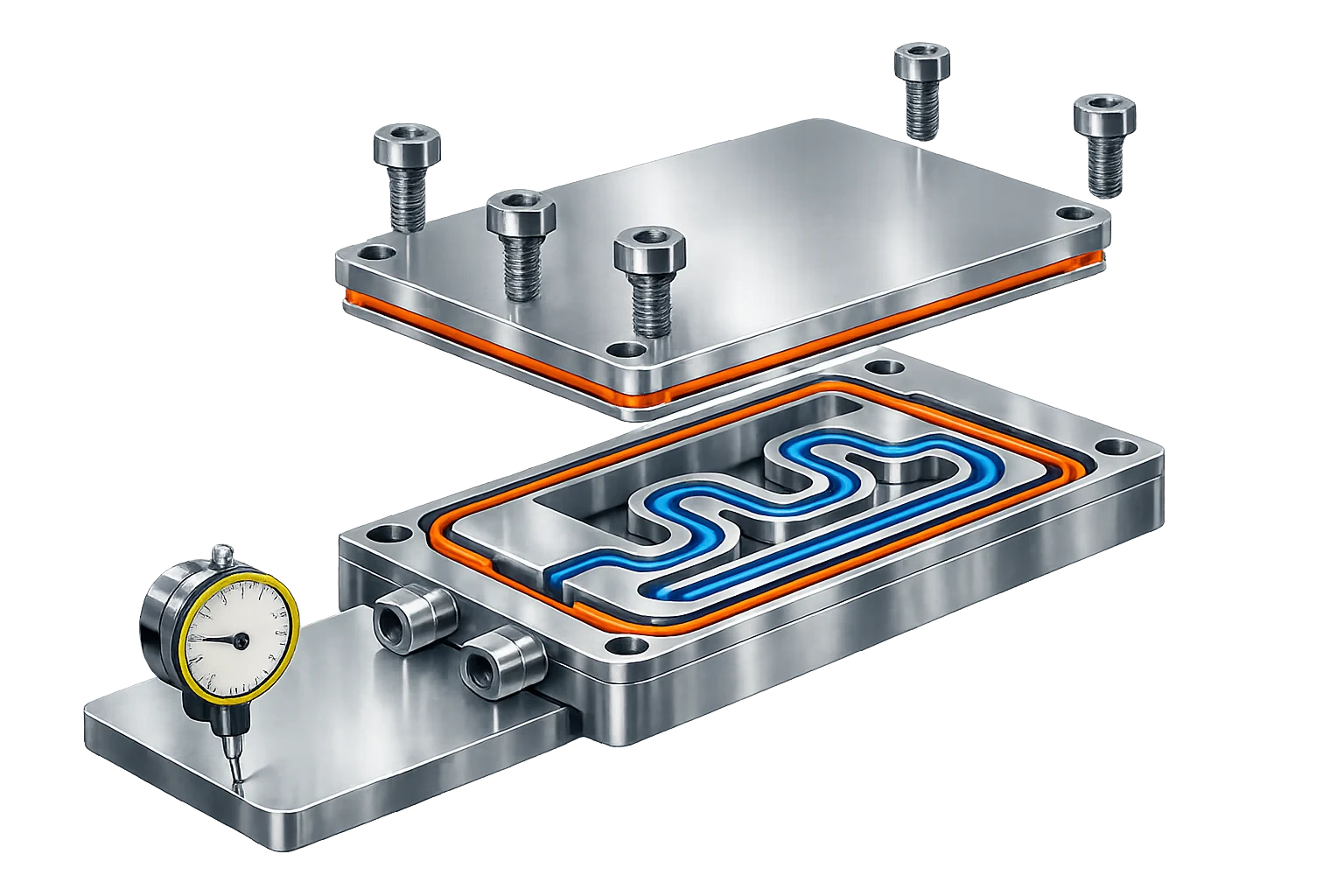
Free-state flatness
Shows the true part shape without external load and helps isolate machining or thermal distortion.
Assembled flatness
Measured under specified fastener torque and sequence to represent the working condition.
Seal compression state
Confirms that groove depth, seal compression, cover stiffness, and preload work together.
For larger cold plates, retain a point map or surface map instead of only the maximum-minus-minimum value. The same total flatness can represent bow, twist, edge lift, or a local bump, and these shapes do not produce the same thermal-interface behavior.
3. More compression does not automatically improve sealing
| Design variable | Too little | Too much |
|---|---|---|
| Seal compression | Incomplete contact and low-pressure leakage | Set, friction damage, and reduced life |
| Groove depth/width | Unstable seal seating | Seal movement, extrusion, or twist |
| Surface condition | Microscopic leakage path | Excessive processing without added benefit |
| Bolt spacing | Local low compression | More hardware and assembly cost |
| Cover stiffness | Pressure bulging | Added weight, cost, and thermal resistance |
Many sealing failures begin as structural-deformation problems rather than seal-material problems.
Groove dimensions, cover thickness, fastener layout, and proof-pressure deflection should be reviewed as one tolerance and load chain.
| Structure | Main risks | Verification focus |
|---|---|---|
| O-ring and bolted cover | Uneven compression, loosening, assembly variation | Groove geometry, torque sequence, assembled flatness |
| Sheet gasket | Local low clamping force and creep | Contact width, surface state, long-term compression |
| Brazed/diffusion-bonded | Incomplete bonding, pores, thermal distortion | Joint integrity, post-cycle leakage and flatness |
| FSW/welded | Weld defects and residual stress | Weld continuity, distortion, machining allowance |
4. Why pneumatic tests can show false leaks or false passes
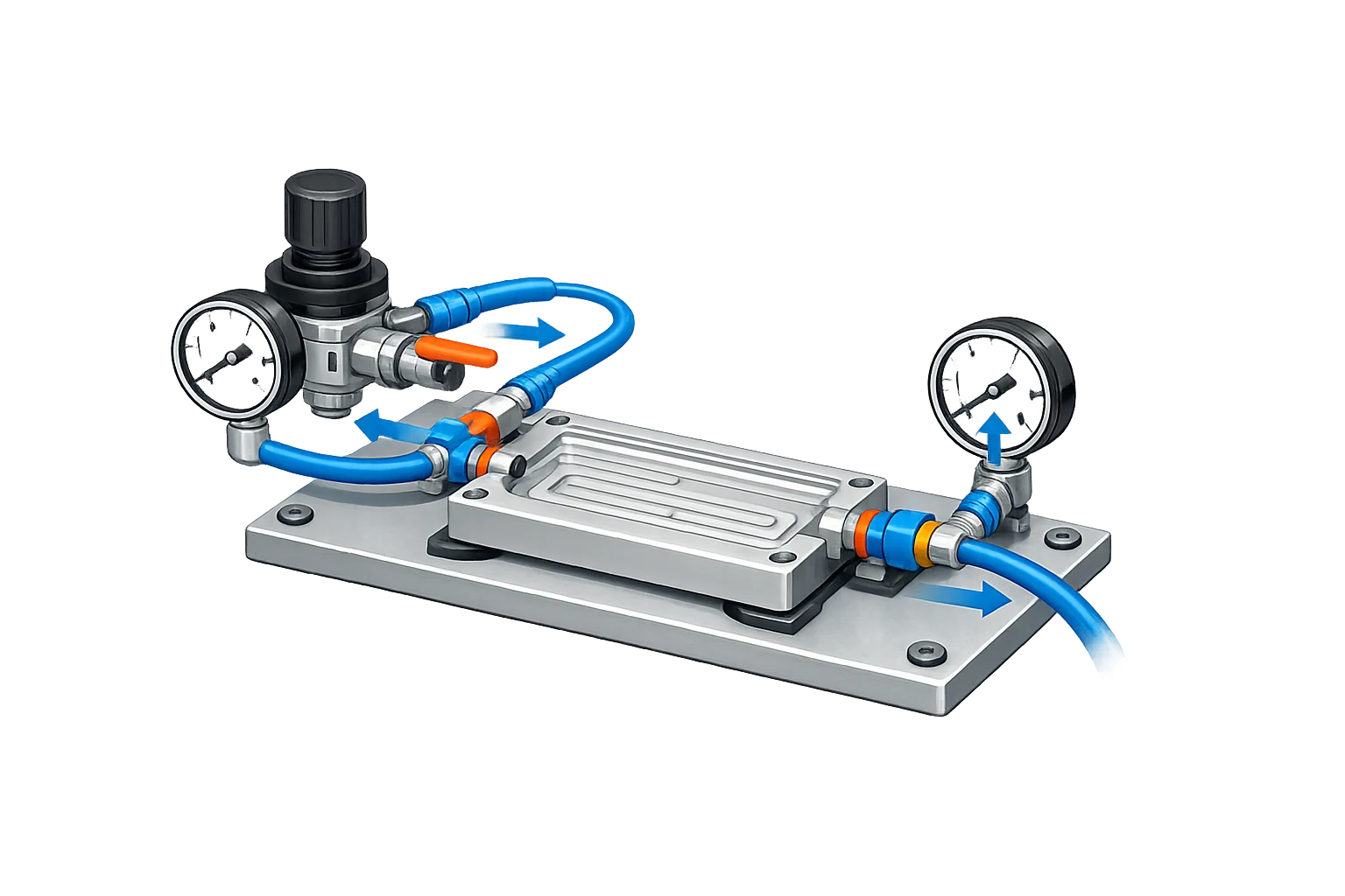
Because gas is compressible, pressure readings are influenced by part temperature, trapped volume, hose expansion, seal settling, and fixture leakage. Starting the measurement immediately after filling often converts thermal stabilization into an apparent leak.
The fixture must also be qualified independently. Otherwise, the measured result represents the combined leakage of the part, fittings, hoses, valves, and plugs.
- 01Connect and plugVerify fittings, plugs, seals, and fixture condition.
- 02Ramp pressureAvoid uncontrolled shock and observe abnormal deformation.
- 03Isolate supplyTurn the test loop into a closed measured volume.
- 04StabilizeAllow temperature, seals, and structure to settle.
- 05MeasureRecord pressure decay, flow, or tracer-gas signal.
- 06Depressurize safelyRelease pressure before disconnecting the part.
| Method | Strength | Limitation | Typical use |
|---|---|---|---|
| Pressure decay | Easy to automate | Sensitive to temperature and volume | Process and final inspection |
| Flow-based leak test | Direct leak-flow output | Higher fixture and equipment demand | Stable mass production |
| Bubble test | Visual and useful for locating leaks | Subjective and requires cleaning/drying | Prototype and failure analysis |
| Tracer gas | High sensitivity and localization | Higher cost and complexity | High-reliability validation |
The same pressure-decay number represents different leak levels when internal volume, temperature, or measurement duration changes. Production records should not store pressure drop alone.
5. Leak, proof-pressure, and burst tests have different purposes
Leak test
Checks leakage under a defined medium, pressure, and duration.
Proof-pressure test
Checks cracking, permanent deformation, fitting movement, and seal failure.
Burst test
Explores design limits by validation sampling and is not a routine shipment test.
There is no universal proof-pressure multiplier. The correct factor depends on operating pressure, pressure spikes, temperature, medium, material strength, fitting rating, customer specification, and safety classification.
The key proof-pressure result is not that the gauge stayed up. The product must still meet flatness, joint integrity, leak, and required flow performance after pressure is removed.
Post-proof checks should normally include visual inspection, fitting condition, contact-surface flatness, repeated leak testing, and—when relevant—flow and pressure-drop verification.
6. Flatness measurement needs repeatable conditions
| Control item | Recommended practice |
|---|---|
| Temperature | Stabilize the part and instrument before measurement |
| Support | Define three-point support or a dedicated fixture |
| Datum | Identify the thermal surface, sealing plane, and mounting datum |
| State | Separate free-state, assembled-state, and post-pressure conditions |
| Sampling | Cover center, edges, fittings, and heat-source regions |
| Data | Retain surface maps or point data, not only one final value |
Common methods include a surface plate with height measurement, CMM scanning, profilometry, or optical methods. The right method is not simply the instrument with the highest resolution; the range, repeatability, fixturing, and cycle time must match the tolerance and production need.
A more useful evaluation separates global form error—bow, twist, or thermal distortion—from local contact defects such as bumps, burrs, tool marks, or fitting-induced deformation.
7. Recommended verification sequence
- 01Visual and cleanlinessInspect grooves, channels, fittings, and surfaces.
- 02Critical dimensionsMeasure seal groove, ports, walls, and assembly datums.
- 03Initial flatnessStore the free-state baseline.
- 04Leak testConfirm fixture background before stabilization and measurement.
- 05Proof pressureRamp pressure and monitor the structure and seals.
- 06Post-pressure checksRepeat leak and flatness checks, plus flow when needed.
New structures, material changes, joining changes, and seal changes may also require temperature cycling, pressure cycling, coolant compatibility, and extended dwell validation. Design validation does not replace production control, and routine production testing does not replace design validation.
8. In mass production, the test system itself is a CTQ
Fixture background check
Use a closed reference part to monitor hoses, valves, plugs, and fittings.
Golden part and leak standards
Verify that the system distinguishes known-good and known-leak conditions.
Measurement-system analysis
Confirm repeatability, reproducibility, resolution, and boundary-part discrimination.
Traceable records
Store product, device, fixture, pressure curve, temperature, operator, and result.
| Category | Minimum useful record |
|---|---|
| Product | Part number, serial number, lot, and design revision |
| Conditions | Medium, fill pressure, stabilization, measurement time, temperature |
| Equipment | Tester ID, fixture ID, range, and calibration state |
| Results | Initial pressure, final pressure, decay/leak rate, proof status |
| Recheck | Post-proof leak, flatness, and flow/pressure drop |
| Failure | Leak location, rework, and retest result |
9. Fast failure interpretation
| Symptom | Check first |
|---|---|
| High test-to-test variation | Stabilization, temperature, connector repeatability, fixture background |
| Leaks at low pressure but not high pressure | Pressure-assisted seal compression |
| Leak test passes but flow is low | Blockage, deformation, contamination, or maldistribution |
| Flatness worsens after proof pressure | Cover bulging, plastic deformation, residual-stress release |
| Repeated leakage near fittings | Threads/joints, fitting load, external hose side force |
| Thermal performance varies while all tests pass | Local surface form, TIM, clamping, or flow distribution |
A strong test guide does not merely add more inspections. It creates a clear path from each symptom back to structure, assembly, the test system, and the real operating condition.
10. Information required before RFQ or design freeze
Define normal operating pressure, peak pressure, coolant and temperature range, leak-test medium and limit, stabilization and measurement time, proof pressure and post-proof checks, free-state and assembled flatness, seal and groove geometry, fitting and piping loads, flow/pressure-drop limits, cleanliness, and the difference between prototype validation, type testing, and shipment inspection.
Without these definitions, a supplier’s statement that the cold plate “passed the leak test” may not correspond to the actual application.
FAQs
Does a passed leak test prove that a cold plate is fully reliable?
No. Leak testing confirms leakage performance under defined conditions, but flatness, proof pressure, flow, pressure drop, cleanliness, and required cycling tests still need separate verification.
What is the difference between leak testing and proof-pressure testing?
Leak testing measures leakage or pressure decay. Proof-pressure testing checks whether the structure suffers permanent deformation, cracking, fitting movement, or seal failure under a defined pressure.
Should flatness be measured before or after assembly?
Critical programs should define both free-state and specified clamped-state flatness because covers, brazing, fastener preload, and system mounting can all change the contact surface.
Why can repeated pressure-decay tests give different results?
Typical causes are temperature change, insufficient stabilization time, fixture leakage, internal volume change, connector repeatability, and inadequate instrument resolution.
