
In This Article
Direct Answer
Cold plate leakage is not only a weld issue. It can originate in design, machining, joining, assembly, testing or service conditions.
| Risk layer | Typical issue | Main control |
|---|---|---|
| Design | Narrow sealing land, thin-wall deformation, unsuitable port loads | DFM, tolerance-chain and pressure-temperature review |
| Machining | Tool marks, burrs, scratches and edge breakout | Datum control, deburring, protection and cleaning |
| Joining | Incomplete bonding, porosity, root defects or abnormal filler flow | Process window, monitoring, section and sample validation |
| Assembly | Twisted seals, uneven torque and connector variation | Error-proofing, torque sequence and assembly records |
| Testing | Temperature drift, fixture background and short stabilization | Reference parts, blank-fixture checks and MSA |
| Service | Pressure pulsation, thermal cycling, corrosion and fluid incompatibility | Reliability validation and materials compatibility |
Effective quality control follows a closed loop:
Risk identification → process prevention → layered leak testing → failure localization → data traceability → corrective action
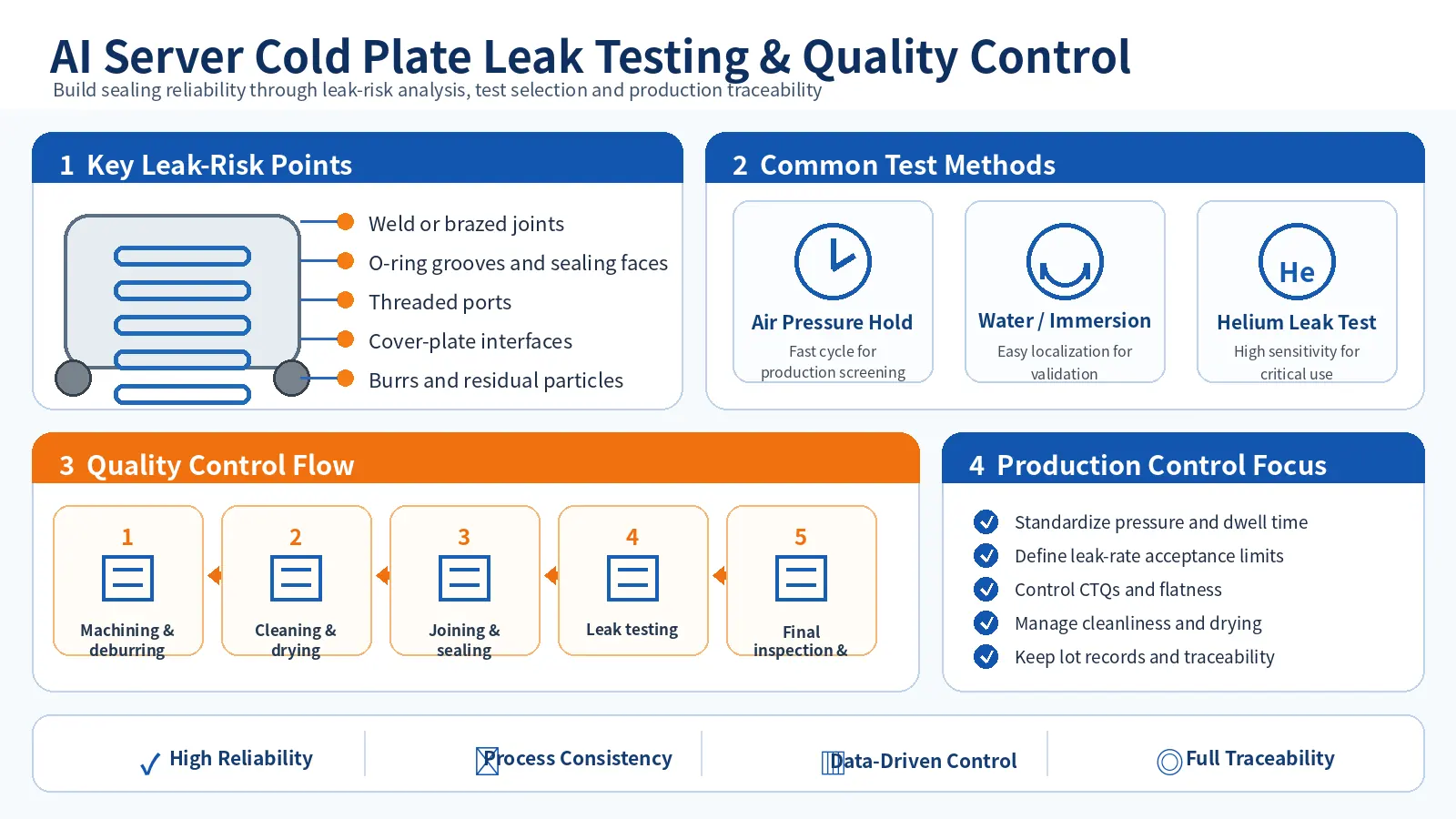
Key leak-risk points, common testing methods, manufacturing flow and production controls for cold plates.
1. Separate Three Different Leakage Problems
1.1 Real External Leakage
Test gas or coolant travels from the internal circuit to the outside. Common locations include cover joints, ports, threads, plugs, seals, weld start-stop zones and machining damage.
1.2 Internal Cross-Leakage
Fluid crosses between passages or cavities that should remain separated without escaping to the outside. A normal external leak test may not find this condition. Sectional isolation, independent circuits or flow and pressure-drop verification may be required.
1.3 Test-System Effects
The product may be acceptable while temperature change, volume variation, hose expansion, valves, fittings or fixture leakage creates a false failure. The reverse is also possible when sensitivity is insufficient, the measurement time is too short or compensation is incorrect.
Before repairing the part, determine whether the signal comes from the product, fixture, instrument or test condition.
2. Common Leak Sources and Manufacturing Causes
| Leak location | Common manufacturing cause | Evidence to review |
|---|---|---|
| Vacuum-brazed interface | Uneven gap, contamination, insufficient or displaced filler, furnace movement | Assembly record, furnace profile, section and leak location |
| FSW path | Root lack of bonding, tunnel defect, poor start-stop treatment, insufficient support | Parameters, axial force, tool condition and path position |
| Laser weld | Excessive gap, unstable penetration, porosity, lack of fusion or burn-through | Weld data, visual result, section or online monitoring |
| O-ring seal | Incorrect groove, compression error, twisting or contamination | Groove dimensions, seal lot and assembly condition |
| Thread or connector | Thread damage, unsuitable sealing method or unstable torque | Gauging, torque record and connector replacement history |
| Cross-hole or plug | Burrs, edge breakout or abnormal plug installation | Hole-edge condition, plug dimension and process parameters |
| Thin wall or port root | Over-machining, pressure deformation, handling damage or fatigue | Wall thickness, flatness and dimensions before and after pressure |
| Corroded area | Incompatible materials, coolant, residue or surface treatment | Wetted materials, cleaning record, fluid and life conditions |
Leak location identifies where failure occurred, but not necessarily the root cause. Leakage near a port may result from the connector, port-root stress, joining distortion or side loading during assembly.
3. Manufacturing Precision Defines Initial Reliability, but Tolerance Alone Is Not Enough
A common cold-plate failure pattern is that the prototype looks acceptable and the CFD result appears reasonable, yet leakage, pressure-drop drift or low yield emerges in production. The issue is often not the concept itself, but the failure to convert machining, joining, cleaning, assembly and testing details into a stable manufacturing window.
Internal passages, thin fins and sealing boundaries must satisfy heat transfer, hydraulic resistance, strength and manufacturability at the same time. Public manufacturing examples sometimes quote tolerance levels such as ±0.02 mm, but this is project-specific and should not be treated as a universal cold-plate requirement. CTQs should be derived from functional failure:
| Manufacturing characteristic | Possible system effect | Recommended control |
|---|---|---|
| Channel width, depth and fin thickness | Pressure drop, flow distribution and heat-transfer variation | First-article measurement, tool-life and trend control |
| Cover flatness and joint gap | Incomplete joining, local distortion and leakage | Datum system, fixturing and pre-join inspection |
| Seal-groove geometry and surface | Incorrect seal compression, cutting or slow leakage | Groove width/depth, radius, finish and cleanliness |
| Port position, thread and face | Connector side load and unstable sealing | Position, thread gauging, face control and torque |
| Burrs, chips and internal residue | Local blockage, rising pressure drop and pump load | Deburring, washing, drying and cleanliness verification |
| Pre-join surface cleanliness | Porosity, lack of bonding or abnormal filler flow | Cleaning time limit, contamination prevention and lot record |
FSW can reduce the broad heat effects associated with fusion welding, but it is not automatically leak-free. Root bonding, tunnel defects, start-stop treatment, axial force, tool wear and backing support still require control. Materials and surface treatment must also be evaluated with the complete wetted-material set, coolant, temperature, conductivity, coating integrity and subsequent joining and sealing requirements.
High-reliability production depends less on one machine than on linking material certificates, tool and joining parameters, SPC trends, cleanliness, leak data and proof-pressure data to the same lot and serial number.
4. Cold Plate Leakage Must Be Analyzed at System Level
Leakage points are not limited to the cold plate. Piping, hoses, quick connectors, valves, manifolds, heat exchangers, pumps, seals and fill/drain interfaces can all fail. Even a conforming cold plate is later exposed to transport vibration, assembly side loads, temperature change, pressure pulsation, maintenance disconnection and coolant aging.
System failures often develop as a chain:
Material or coolant incompatibility → corrosion and debris → filter or microchannel blockage → rising pressure drop → falling flow → local overheating → higher pump load → expanded leakage or shutdown risk
Reliability should therefore be designed in four stages:
- Prevent: control compatibility, structural strength, connection design, cleanliness and assembly;
- Detect early: combine leak, pressure, flow, temperature, liquid-level and pump-status monitoring;
- Control safely: define alarm, workload reduction, valve isolation, pump transfer and shutdown sequence;
- Recover quickly: isolate the failed loop, replace parts, trace data and reproduce the cause.
The presence of a sensor does not guarantee detection. The leaked liquid must reach the sensor, broken wiring must be diagnosed, and pressure or flow readings must remain consistent with temperature behavior. No single measurement should be the only safety barrier.
A cold-plate supplier should deliver more than dimensional acceptance and a leak-test PASS. Useful engineering data include the flow-pressure-drop curve, wetted-material list, internal cleanliness, pressure and temperature limits, test conditions, port assembly requirements and lot traceability.
5. Simulation First: Validate Thermal, Hydraulic and Structural Risk Before Cutting Metal
A successful simulation does not guarantee leak-free production, but the absence of simulation allows system-level risks to remain hidden until prototype or deployment. Cold-plate development should connect CFD, structural analysis and physical correlation instead of treating them as substitutes.
The design stage should answer at least:
- whether flow is balanced across parallel channels, manifolds and multiple cold plates;
- whether local resistance creates hotspots, recirculation or trapped gas;
- whether pump starts, valve actions and pressure transients can create water-hammer loads;
- whether differential thermal expansion of metals, polymers and seals loads the ports;
- whether piping and equipment vibration transfers cyclic load into fittings, joints and thin walls;
- how manufacturing tolerance, roughness and channel variation affect pressure drop and temperature distribution.
| Simulation question | Required physical validation |
|---|---|
| Flow distribution and hotspots | Flow, pressure drop, inlet/outlet temperature and thermal test |
| Pressure pulsation and water hammer | Transient-pressure recording, proof and pressure cycling |
| Thermal expansion and deformation | Thermal cycling, flatness, port displacement and post-cycle leak test |
| Vibration and piping load | Boundary-defined vibration test and post-test leakage |
| Performance sensitivity to tolerance | Limit samples or statistical-tolerance validation |
| Sensor and fault logic | Fault injection for disconnection, drift, low flow and leakage |
“Simulation First” is valuable because it identifies risk and defines CTQs and test boundaries before production. Monitoring can detect a problem but cannot repair an inherently poor flow topology; simulation cannot replace physical leak, proof-pressure, flow, thermal and life testing. The correct loop is:
Simulation prediction → prototype correlation → model correction → design lock → production monitoring
6. Why Pressure-Decay Testing Is Sensitive to Temperature
Pressure-decay testing normally includes filling, stabilization, isolation and measurement. Rapid gas compression raises temperature. Cooling afterward lowers pressure even when the part is perfectly sealed.
Major variables include:
- internal volume;
- fill rate and test pressure;
- part, gas and ambient temperature;
- stabilization and measurement time;
- elastic behavior of hoses, valves and fixtures;
- connector repeatability;
- instrument resolution and compensation.
| Observation | Possible cause | Recommended check |
|---|---|---|
| Repeated results drift on the same part | Thermal instability or connection variation | Extend stabilization and standardize connection |
| Entire batch suddenly shifts | Fixture, hose, valve or calibration issue | Run blank fixture and golden part |
| Large-volume part gives unstable results | Volume and temperature effects are amplified | Revalidate cycle time and compensation |
| Borderline sample alternates pass/fail | Insufficient resolution or repeatability | Perform MSA with calibrated leak standards |
| Leakage appears after proof pressure | Permanent deformation or defect growth | Recheck dimensions, joint and proof conditions |
Pressure-decay testing is suitable for automated production only after repeatability, fixture background and the temperature window are demonstrated.
7. Different Leak-Test Methods Answer Different Questions
| Method | Main advantage | Main limitation | Typical use |
|---|---|---|---|
| Pressure decay | Fast and easy to automate | Sensitive to temperature, volume and fixture | Production and final inspection |
| Mass-flow testing | Direct leakage-flow output | Higher equipment and fixture demands | Stable production and limit control |
| Bubble testing | Visual and useful for locating larger leaks | Subjective and adds cleaning/drying work | Prototype, rework and failure analysis |
| Tracer-gas sniffing | Localizes small leaks | Operator path and background affect results | Failure analysis and local inspection |
| Tracer-gas vacuum chamber | High sensitivity and repeatability | Higher cost, cycle-time and fixture complexity | High-reliability validation and automation |
| Hydrostatic proof test | Suitable for structural loading | Does not provide high-sensitivity leak rate by itself | Structural and proof-pressure validation |
Tracer-gas testing still requires a defined method, gas concentration, calibrated leak, background control and acceptance limit. “Helium test required” alone is not a complete specification.
8. Leak, Proof and Burst Tests Must Be Defined Separately
Leak Test
Measures pressure change, flow or tracer-gas leak rate under specified conditions.
Proof-Pressure Test
Checks that the assembly does not rupture, leak or undergo unacceptable permanent deformation.
Burst Test
Studies the structural limit and failure mode, normally during design validation or sampling.
A universal pressure multiplier should not be applied without the product boundary. Maximum operating pressure, transient pressure, coolant, temperature, material condition, connector rating, customer specification and safety requirements all matter.
After proof pressure, verify at least:
- appearance and permanent deformation;
- connectors, threads and plugs;
- thermal-contact and mounting datums;
- leakage again;
- flow and pressure drop when required.
9. What a Usable Leak-Test Specification Must Define
| Item | Required definition |
|---|---|
| Test state | Bare part, assembled part, specified torque or system state |
| Test medium | Dry air, nitrogen, tracer gas or specified liquid |
| Pressure | Fill, operating, proof and allowed variation |
| Time | Fill, stabilization, measurement and venting time |
| Temperature | Allowed ambient, part and medium range |
| Volume | Part volume, connected piping and compensation chamber |
| Fixture | Port interface, seals, fixture ID and background leakage |
| Instrument | Range, resolution, calibration and repeatability |
| Acceptance | Pressure decay, leak flow or tracer-gas leak rate |
| Traceability | Part lot, serial number, equipment, fixture, program and operator |
“Zero leakage,” “no pressure drop” or “pressure hold passed” is incomplete because every method has a detection boundary.
10. Layered Validation from Prototype to Production
- 01Design ReviewIdentify joint boundaries, seal grooves, port loads, thin walls and corrosion risks.
- 02Engineering SamplesValidate structure and process using leak, proof, flow, pressure-drop and section evidence.
- 03Reliability ValidationApply temperature cycling, pressure cycling, vibration and fluid compatibility as required.
- 04Production ReadinessFreeze fixtures, cycle time, reference parts, acceptance window and reaction plan.
- 05Stable ProductionStore curves and batch data and monitor trends instead of recording only PASS/FAIL.
Production leak testing can screen nonconforming parts, but it cannot replace design validation. Reliability testing demonstrates the design boundary, but it does not replace control of every production part.
11. Recommended Reaction to a Production Leak Failure
| Sequence | Action | Purpose |
|---|---|---|
| 1 | Stop release and isolate the current lot | Prevent further escape |
| 2 | Check blank fixture, golden part and calibrated leak | Separate equipment from product |
| 3 | Repeat the test and save the complete curve | Identify thermal, slow-leak or connection effects |
| 4 | Localize the leak | Separate joints, ports, plugs and seals |
| 5 | Compare material, machining, joining, assembly and test lots | Find the common change point |
| 6 | Validate containment and permanent correction | Close the root cause, not only rework |
| 7 | Update control plan, process window and inspection frequency | Convert learning into sustained control |
The abnormal record should include part number, revision, lot, serial number, equipment, fixture, program, temperature, pressure curve, leak location, repair method, retest result and root-cause analysis.
12. Information Required for RFQ and Engineering Review
| Information group | Recommended content |
|---|---|
| Product data | 2D drawing, 3D model, revision, prototype and annual volume |
| Structure | Flow paths, joints, seal grooves, ports and thin-wall areas |
| Pressure | Operating, transient, proof, burst or customer standard |
| Leakage | Method, medium, limit, stabilization and measurement time |
| Wetted conditions | Coolant, temperature range, material combination and finish |
| Reliability | Temperature cycling, pressure cycling, vibration and life |
| Traceability | Serial number, lot, curve storage and report format |
| Nonconformance | Rework limits, retest and change-approval requirements |
Frequently Asked Questions
Does a stable pressure-hold result prove that a cold plate has absolutely no leak?
No. It only shows that no leak above the acceptance threshold was detected under the specified medium, pressure, temperature, stabilization time, measurement time and instrument resolution. Small leaks, poor temperature compensation or fixture-background leakage can still affect the result.
Why can pressure-decay testing produce false failures or false passes?
Common causes include gas-temperature change after filling, insufficient stabilization time, fixture or connector leakage, differences in internal volume, hose expansion, valve condition and ambient-temperature variation.
Can leak testing and proof-pressure testing be combined into one step?
They should not be treated as the same test. Leak testing measures leakage or pressure change, while proof-pressure testing evaluates structural integrity and permanent deformation. After proof pressure, the part should be checked again for leakage, appearance, critical dimensions and flow or pressure drop when required.
What should be checked first after a production cold plate fails a leak test?
First separate the test system from the product by checking fixture background, connectors and reference parts. Then use the leak location and batch history to investigate joining zones, port sealing, machining damage, cleanliness, assembly parameters and recent process changes instead of assuming that every failure is a welding defect.
