
In This Article
Direct Answer
Internal cleanliness is a functional quality characteristic, not a cosmetic requirement.
Contamination can block microchannels, filters or quick connectors; increase pressure drop; reduce local heat transfer; raise pump load; damage seals and valves; promote corrosion; and circulate into other system components.
The complete control chain is:
Source identification → process prevention → staged cleaning → extraction and inspection → draining and drying → sealing and packaging → transport and commissioning control
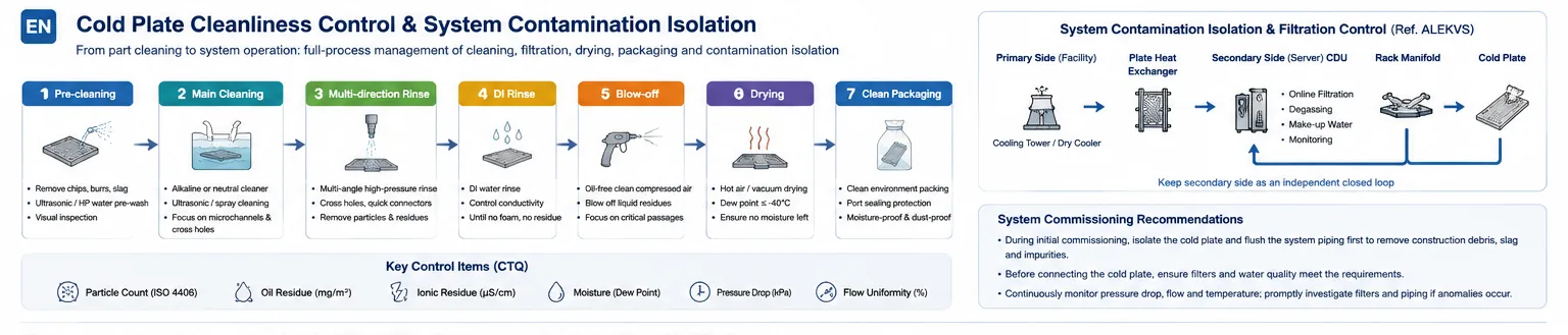
From component cleaning, rinsing, drying and clean packaging to system filtration, contamination isolation and commissioning control.
1. Why Microchannel Cold Plates Are Sensitive to Particles
| Sensitive geometry | Possible problem | Control focus |
|---|---|---|
| Microchannels and thin fins | Particle bridging and local blockage | Minimum passage, burrs and filtration |
| Tight turns and distribution zones | Deposition and recirculation | Transition, flush direction and velocity |
| Cross-holes and plugs | Edge burrs and trapped chips | Deburring, borescope and flush path |
| Ports and quick connectors | Valve sticking and seal damage | Clean interface, caps and FOD-safe assembly |
| Sealed flow paths | Limited access after joining | Pre-join cleaning and post-seal validation |
| Low points and dead zones | Retained fluid and moisture | Drain orientation, purge and drying |
Risk depends on particle shape, hardness, quantity, material, velocity and location—not size alone.
2. Main Contamination Sources
| Contamination | Typical source | Possible effect |
|---|---|---|
| Chips and burrs | Milling, drilling, tapping and deburring | Blockage, scratching and valve damage |
| Abrasives | Grinding, polishing, blasting and tool wear | Hard-particle wear and deposition |
| Machining oil | CNC, fixturing and storage | Coolant contamination and film residue |
| Cleaning residue | Incorrect concentration, time or rinsing | Corrosion, foam and ionic contamination |
| Joining residue | Filler, oxide, spatter and process aids | Particles, corrosion and blockage |
| Seal fragments | O-rings, sealants and thread materials | Valve sticking and passage blockage |
| Retained moisture | Rinse water, poor draining and humid storage | Corrosion and coolant instability |
| Packaging FOD | Fibers, dust, paper and cap debris | Secondary contamination |
The strongest control prevents contamination from entering and becoming trapped at each process step.
3. Extend Cleanliness Control from the Part to the Complete Liquid-Cooling Loop
A cold plate can pass component cleaning and still become contaminated after installation. A complete system normally includes heat rejection, a primary facility loop, a CDU, a secondary technology loop, rack manifolds and cold plates. Long-term cleanliness depends not only on the end component, but also on separation of the primary loop, continuous secondary-loop filtration, air removal and balanced flow distribution.
| System layer | Cleanliness-related function | Interface to define for cold plate manufacturing and acceptance |
|---|---|---|
| Primary facility loop | Connects to facility-side heat rejection and may have different water-quality and contamination conditions | Do not assume primary fluid can directly enter the cold plate |
| Plate heat exchanger | Separates facility and technology fluids | Define materials and fluids for each side independently |
| CDU secondary loop | Controls temperature, pressure and flow on the server side | Cold plate testing should represent the actual secondary-loop boundary |
| Inline filtration | Captures installation residue, wear particles and circulating debris | Define filter level, differential pressure and service strategy |
| Degassing and filling | Reduces trapped air, stagnant zones and pump-cavitation risk | Validate venting, orientation and high-point air traps |
| Rack manifold | Distributes coolant across servers and cold plates | Branch length, resistance and connectors affect flow uniformity |
| Sensors and controls | Monitor pressure, flow and temperature | Cleanliness problems should be detectable through trend changes |
The plate heat exchanger is valuable not only for heat transfer, but also for separating the facility loop from the server-side loop and reducing direct transport of external piping contamination into microchannels. Filtration, degassing and pressure-flow control in the CDU help maintain the secondary loop over time.
The responsibility boundary should therefore be explicit: component cleanliness at shipment, system flushing, final coolant, filter grade, field connection and maintenance handling must each have an owner. “Clean the system after installation” is not a sufficient control plan.
4. Pressure Drop and Flow Uniformity Are Functional Evidence of Cleanliness
Three linked indicators are especially important in cold-plate systems:
- Thermal resistance: the ability to transfer chip heat into the coolant;
- Pressure drop: the pumping cost of moving coolant through the plate and piping;
- Flow uniformity: whether parallel passages, cold plates and server branches receive appropriate flow.
Contamination may first appear as a local resistance increase rather than complete blockage. Total plate flow can still appear acceptable while internal parallel passages become unbalanced and local temperature rises. Unequal manifold branch length and resistance can also starve remote or high-resistance branches, causing system distribution and cleanliness effects to overlap.
Cleanliness verification should therefore connect particle results to hydraulic and thermal evidence:
| Result | Possible meaning | Recommended follow-up |
|---|---|---|
| Particle limit exceeded, pressure drop normal | No major blockage yet, but long-term circulation risk remains | Material analysis, recleaning and life-risk review |
| Pressure drop high, particle test normal | Geometry, deformation, retained fluid or weak extraction method | Dimensions, borescope, flow curve and extraction review |
| Total flow normal, temperature distribution abnormal | Internal maldistribution or local restriction | Multi-point temperature, flow balance and thermal test |
| Remote cold plates receive low flow | Manifold or branch imbalance, not necessarily cold plate contamination | Branch differential pressure, valve state and balancing |
| Pressure drop rises during operation | Inadequate filtration, corrosion products or incompatibility | Filter residue, coolant analysis and materials review |
| Flow signal fluctuates with noise | Trapped gas, poor degassing or cavitation | Venting, degassing, liquid level and pump-inlet conditions |
Production acceptance should retain a flow-pressure-drop baseline at defined fluid and temperature conditions. Comparing field trends with that baseline helps detect blockage, debris, trapped gas and flow-distribution problems earlier.
5. Convert Cleanliness into Measurable CTQs
| CTQ group | Possible metric | Purpose |
|---|---|---|
| Particles | Total count, size classes, largest particle and material | Link to minimum passage and filtration |
| Extractable residue | Filter mass per part | Evaluate total solid contamination |
| Oil and organic residue | Film, fluorescence or specified analysis | Control machining oil and preservative |
| Ionic or cleaner residue | Conductivity, ions or chemistry | Prevent corrosion and coolant contamination |
| Retained moisture | Mass change, dew point or drying criterion | Link to packaging and storage life |
| Flow and pressure drop | Curve at defined fluid and temperature | Demonstrate open passages |
| Visual condition | Ports, sealing faces and borescope zones | Supplement analytical tests |
No single universal cleanliness limit applies to every cold plate.
6. A Practical Cleaning Route
- 01Pre-cleanRemove large chips, loose particles and visible oil.
- 02Main cleanSelect a validated process for the material, geometry and contamination.
- 03Multi-direction flushControl fluid, flow, direction, pressure, temperature and time.
- 04RinseRemove cleaner and soluble residue.
- 05Drain and purgeUse defined orientation and clean air or nitrogen.
- 06Dry and validateConfirm moisture, particles, residue, flow and pressure drop.
- 07Seal and packageCap clean ports and prevent secondary contamination.
Cleaning chemistry must be compatible with all wetted materials and the final coolant.
7. Flushing Parameters Must Be Controlled
| Parameter | Why it matters |
|---|---|
| Fluid | Cleaning ability, corrosion and residue risk |
| Flow and velocity | Particle removal from passages and low points |
| Direction | Coverage of split-flow regions and dead zones |
| Pressure | Effectiveness versus wall and seal safety |
| Temperature | Cleaning, compatibility and drying |
| Time | Adequacy without unnecessary exposure |
| Part orientation | Bubble, particle and liquid drainage |
| Filtration | Preventing removed particles from returning |
| Final rinse | Removal of cleaner and soluble residue |
System-commissioning values should not be copied as universal component-cleaning parameters.
8. Verify Cleanliness
| Method | What it detects | Limitation |
|---|---|---|
| Visual and borescope | Large debris, burrs, corrosion and oil | Visible zones only |
| Flush extraction and membrane | Particle count, size and trend | Fluid, direction and volume must be fixed |
| Gravimetric residue | Total extractable solids | No size or material information |
| Automatic particle count | Size distribution and count | Bubbles and fibers can interfere |
| Microscopy and material analysis | Chips, abrasives and seal fragments | Best for source analysis |
| Organic-residue test | Machining oil and preservative | Must link to allowed residue |
| Conductivity or ionic test | Rinse and ionic-residue trend | Does not represent all contamination |
| Drying verification | Retained liquid and moisture risk | Requires defined timing and limit |
| Flow-pressure-drop test | Blockage and internal variation | Conditions must be fixed |
Reliable verification usually combines several methods.
9. Drying, Sealing and Transport Are Part of Cleanliness
Industry logistics guidance treats removal of test fluid and particles, residual-liquid control, internal protection and complete port sealing as part of cold-plate preparation.
| Stage | Control focus |
|---|---|
| Drain | Defined orientation, time and direction |
| Purge | Clean air or nitrogen |
| Dry | Validated temperature, time and moisture |
| Protect | Nitrogen or specified medium when required |
| Seal ports | Clean, secure, non-shedding caps |
| Package | Dust, moisture, impact and port-load protection |
| Identify | Part, lot, cleaning date and storage life |
| Validate transport | Vibration, temperature and package integrity |
Opening the package should start a defined exposure period.
10. Flush System Piping Before Exposing Cold Plates
New piping, manifolds and fittings can contain construction debris, sealing material and ambient particles. A practical sequence is:
- install new filters;
- isolate cold plates and flush piping/manifolds first;
- drain and inspect or replace filters;
- connect cold plates and repeat the approved flush;
- charge final coolant;
- verify filters, flow, pressure drop, coolant condition and leakage;
- retain commissioning records.
Unvalidated chemical cleaners may create corrosion or residue problems.
11. Reaction to a Production Cleanliness Failure
| Sequence | Action | Purpose |
|---|---|---|
| 1 | Stop release and isolate lots | Prevent contaminated shipment |
| 2 | Check blanks, extraction fluid and inspection equipment | Exclude test contamination |
| 3 | Check tanks, filters, nozzles and purge gas | Confirm cleaning-system condition |
| 4 | Analyze particle size, shape and material | Identify the source |
| 5 | Trace machining, deburring, joining, cleaning and packaging | Find the common change |
| 6 | Check flow, pressure drop, leakage and internal condition | Assess functional risk |
| 7 | Validate reclean or scrap decision | Avoid repeated-cleaning damage |
| 8 | Update controls and preventive action | Close the root cause |
Increasing cleaning time alone is not a complete corrective action.
12. Information Required for RFQ
| Information | Recommended content |
|---|---|
| Geometry | Minimum passage, cross-holes, dead zones and ports |
| Materials | Aluminum, copper, stainless, filler, coating and seals |
| Coolant | Type, additives, temperature and compatibility |
| Filtration | System filter, valves and quick-connector sensitivity |
| Particle standard | Count, size classes, largest particle and extraction |
| Chemical residue | Oil, ions, cleaner and test method |
| Drying | Moisture limit, purge medium and storage life |
| Hydraulic performance | Flow and pressure drop at defined conditions |
| Packaging | Nitrogen, caps, bag, label and transport validation |
| Traceability | Lot, equipment, program, result and report |
Frequently Asked Questions
If no contamination is visible inside a cold plate, does that prove cleanliness?
No. Microchannels, cross-holes and sealed passages cannot be fully inspected visually, and small particles, oil films, ionic residues or retained moisture may still be present. Verification requires a defined extraction, filtration, particle or residue test.
Can strong alkaline or acidic cleaners be used directly for cold plate cleaning?
They should not be applied without validation. The cleaner must be compatible with aluminum, copper, stainless steel, filler metal, coatings, seals and the final coolant, and the rinse process must demonstrate that harmful residue is not retained. Unapproved chemical cleaners should not be used without confirmation from the fluid or material supplier.
Why should flow and pressure drop be checked after cleaning?
Cleaning must demonstrate not only that obvious contamination is removed, but also that particles, deformation or local blockage have not affected the internal passages. Abnormal flow or pressure drop can indicate cleanliness, dimensional or internal-damage problems.
Why can contamination appear at the customer site after a cold plate passed cleaning?
Common causes include retained moisture, unsealed ports, damaged packaging, particles generated during transport, debris in site piping and an incorrect commissioning flush sequence. Cleanliness must be managed together with drying, sealing, packaging, transport and system commissioning.
