
In This Article
Direct Answer
A cold plate joining process should not be selected by asking which welding technology is the most advanced. It should be selected from the cold plate architecture and the required evidence of performance.
| Project condition | Joining process to evaluate first | Main reason |
|---|---|---|
| Multilayer channels, internal fins, separators or multiple joints | Vacuum brazing | Multiple internal interfaces can be joined in one thermal cycle |
| CNC-machined channel base with an inserted cover and a fully accessible path | Friction stir welding (FSW) | Solid-state joining along a continuous closure path |
| Thin cover, narrow closed seam and high-speed automation | Laser welding | Non-contact process with concentrated heat input |
| Prototype design still changing | Manufacturability samples first | Revision speed matters more than single-part takt |
| Very strict leakage and life requirements | Joining and validation plan together | Seam appearance or one leak test is not enough |
The real comparison is the complete manufacturing chain:
Base and cover machining → cleaning → location and assembly → joining → post-join machining → internal cleaning and drying → dimensional inspection → leak and proof-pressure testing → flow and pressure-drop validation → thermal and reliability validation
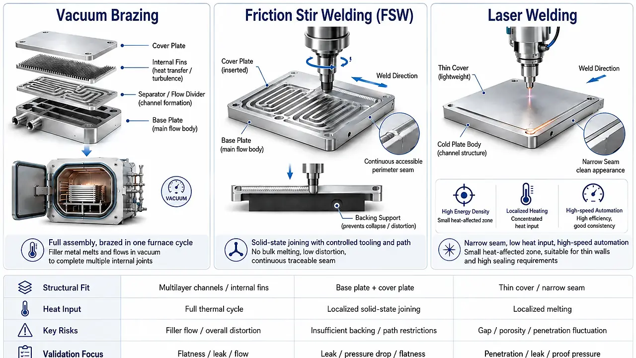
Comparison of structural fit, heat input, key risks and validation priorities for three cold plate joining processes.
1. Separate Channel Manufacturing from Cover Joining
| Decision level | What must be defined | Typical options |
|---|---|---|
| How the channel is formed | How the base, flow paths, fins and distribution features are made | CNC machining, extrusion, stamping, deep drilling, microchannels, layered construction |
| How the channel is closed | How the base, channel layer and cover become a sealed assembly | Vacuum brazing, FSW, laser welding, mechanical sealing |
| How the assembly is validated | How dimensional, sealing and thermal performance are demonstrated | Flatness, leak, proof pressure, flow, pressure drop, thermal resistance, thermal cycling |
CNC machining, extrusion and stamping mainly address part and channel formation. Vacuum brazing, FSW and laser welding mainly address joining and closure.
2. Vacuum Brazing: Value in Complex Internal Structures
A vacuum-brazed cold plate may contain a base, channel layers, internal fins, separators, a cover and port components. Its key advantage is the ability to form internal joints that no external tool or laser beam can trace individually.
Suitable structures
- multilayer flow paths;
- internal fins or turbulence features;
- multiple covers, separators or ports;
- internal interfaces inaccessible to an FSW tool or laser beam;
- stable products that support a controlled assembly and furnace process.
Critical controls
| Control item | Risk when uncontrolled |
|---|---|
| Surface flatness and joint clearance | Local non-bonding or uneven filler distribution |
| Filler location and quantity | Leakage or filler entering narrow channels |
| Cleaning and drying | Oxides, contamination and unstable wetting |
| Assembly location and restraint | Movement and datum shift in the furnace |
| Full thermal cycle | Sag, bow, temper change and dimensional movement |
| Post-braze allowance | Inability to restore thermal and mounting datums |
Vacuum brazing should be distinguished from flux-based controlled-atmosphere brazing. Vacuum brazing commonly uses clad sheet or preplaced filler and relies on vacuum, material selection and strict surface preparation. Flux residue is not an unavoidable condition of every vacuum-brazed part.
Validation should include flatness, datums, leak, proof pressure, flow, pressure drop, cleanliness and, where required, internal inspection, thermal cycling and thermal performance.
3. Friction Stir Welding: Strong Fit for a Machined Base and Cover
FSW uses a rotating tool to create frictional heat and plastic flow without bulk melting. It is commonly used around an inserted cover or along designed closure paths.
Five manufacturability checks
- Full tool access: ports, bosses, holes, corners, start and stop zones must not block the tool.
- Backing below the seam: insufficient land width or wall thickness can cause channel intrusion or deformation.
- Uniform clamping: thin covers require continuous backing and controlled hold-down.
- Balanced sequence: large or multi-path plates may need center-out, symmetric or alternating paths.
- Recorded parameters: spindle speed, travel speed, axial force, plunge depth and tool condition require a defined production window.
| Risk | Possible result | Control focus |
|---|---|---|
| Inaccessible tool path | Interrupted or incomplete closure | Review access before design freeze |
| Gap between cover and base | Local thinning or unstable joining | Control flatness and fixture hold-down |
| Insufficient backing below seam | Channel intrusion or deformation | Design support lands and validate axial load |
| Unstable parameter window | Tunnel, root or surface defects | Monitor speed, force and plunge depth |
| Poor start/stop treatment | Exit-hole or local leak risk | Reserve a non-functional zone or use special tooling |
FSW reduces many fusion-welding problems, but it is not a zero-distortion process and does not replace flatness, leak and flow validation.
4. Laser Welding: Thin Covers and High-Speed Automation
Laser welding creates a localized weld pool with a high-energy-density beam. It is non-contact, fast and easy to integrate into automation.
Suitable structures
- thin covers and thin-wall assemblies;
- regular seams with beam access;
- high-speed continuous production;
- low overall heat exposure;
- stable location, clamping and monitoring.
Key controls include fit-up, seam location, oil and oxide removal, focus position, power, speed, beam distribution, penetration, porosity, spatter, lack of fusion and burn-through.
Aluminum reflectivity, oxide films and weld-pool stability add development difficulty. Stable production often depends on application-specific optics, fixtures, path compensation and process monitoring, not simply more laser power.
A continuous surface seam does not prove long-term sealing. Visual inspection should be combined with leak, proof-pressure, section or other verification, plus thermal cycling or vibration where required.
5. Process Comparison
| Comparison item | Vacuum brazing | Friction stir welding | Laser welding |
|---|---|---|---|
| Typical structure | Multilayer, internal fins, multiple joints | Machined base with inserted cover | Thin cover and narrow closed seam |
| Joining state | Filler melts; base does not bulk melt | Solid-state plastic joining | Local fusion welding |
| External access | No tool traces each internal interface | Tool follows the full path | Beam reaches the full seam |
| Filler | Clad layer or preplaced filler | Usually none | Autogenous or filler-assisted |
| Main thermal effect | Full furnace cycle | Local thermo-mechanical effect | Highly localized heat input |
| Fit-up sensitivity | Clearance, filler, cleaning, location | Contact, backing, clamping, path | Gap, position, surface and focus |
| Main defect risks | Non-bonding, filler-flow variation, global distortion | Tunnel, root defect, channel intrusion, exit region | Porosity, lack of fusion, penetration variation, burn-through |
| Post-join focus | Flatness, datum recovery, cleanliness | Start/stop region, flatness, leak, flow | Seam continuity, penetration, leak, proof pressure |
| Production model | Furnace batch | Dedicated machine or CNC-style processing | High-speed automated welding |
| Best design value | Internal structural freedom | Stable base-and-cover closure | Thin parts, speed and low overall heat |
6. Do Not Compare Welding Speed Alone
The full cost includes part machining, cleaning, fixturing, joining, post-processing, internal cleaning, dimensional inspection, leak and proof-pressure tests, flow and pressure-drop validation, and reliability testing.
A fast seam may still carry high total cost when fixtures are complex, rework is difficult or extensive post-join machining is required.
7. Re-Evaluate from Prototype to Production
| Stage | Main objective | Evidence required |
|---|---|---|
| Concept prototype | Validate channels, ports and initial sealing | Dimensions, leak, flow and basic thermal performance |
| Engineering validation | Confirm CTQs and reliability | Proof pressure, pressure drop, flatness, cleanliness, thermal cycling |
| Production preparation | Establish a process window | Fixtures, parameters, tool life, CTQs and inspection frequency |
| Stable production | Control lot consistency | Process records, traceability, abnormal feedback and change control |
A prototype that can be welded does not prove that the production process is established.
Passing one leak test does not prove channel performance and long-term reliability.
8. Information Needed for RFQ
| Information category | Recommended input |
|---|---|
| Controlled design data | 2D drawing, 3D model, revision and key changes |
| Material and structure | Alloy, temper, base and cover thickness, channels and ports |
| Joining area | Seam path, channel-to-seam distance, access and keep-out zones |
| Performance | Operating pressure, transient pressure, proof pressure, allowable leak, flow and pressure drop |
| Thermal surface | Flatness, roughness, mounting load and post-join machining limits |
| Wetted conditions | Coolant, wetted metals, surface treatment, cleanliness and corrosion requirements |
| Project conditions | Prototype quantity, annual volume, takt, lead time and traceability |
| Reliability | Thermal cycling, vibration, service life and validation standards |
Frequently Asked Questions
Is friction stir welding always better than vacuum brazing?
No. FSW is well suited to base-and-cover structures with an accessible tool path and sufficient backing below the seam. Vacuum brazing is better suited to internal fins, multilayer channels and multiple joints that must be formed in one thermal cycle.
Does a passed leak test prove that the joining process is reliable?
No. A leak test only shows that no leakage was detected under the specified method and sensitivity. Proof pressure, flow, pressure drop, flatness, joint inspection and, where required, thermal cycling and thermal performance must also be verified.
Is FSW or laser welding better for a thin cover plate?
The answer depends on cover thickness, joint gap, seam path, backing support, allowable distortion and production takt. FSW requires reliable support and axial-force control, while laser welding is more sensitive to fit-up, cleanliness, focus position and penetration stability.
What information is needed to quote a cold plate joining project?
Recommended inputs include controlled 2D drawings, 3D models, material and temper, base and cover thickness, distance from channels to seams, operating and proof pressure, allowable leakage, thermal contact surface requirements, coolant, expected volume, thermal cycling and other validation standards.
