
In This Article
Direct answer
The manufacturing challenge in an aluminum front frame for AI smart glasses is not merely machining the outline. The part must combine low mass and a narrow section with control of:
- lens or optical-display seating geometry;
- the relationship between the two lens rims and bridge;
- camera, indicator or sensor windows;
- nose-pad and hinge locations;
- assembly to PA plastic temples and electronic covers;
- cosmetic consistency after anodizing;
- temple angle, optical position and comfort in the worn condition.
Public information confirms CNC precision processing of the metal frame, while other reports describe 5-axis CNC and an anodized matte finish. The exact alloy, temper, stock route, full machining sequence, fixture design, PA reinforcement and metal-to-plastic joining method have not been fully disclosed. The manufacturing route below is an engineering analysis for comparable parts, not a claim about the complete proprietary process of any one product.
define complete-product and optical interfaces
→ evaluate material and stock
→ complete 5-axis CNC and fixturing DFM
→ manage roughing and distortion
→ finish precision interfaces and cosmetic toolpaths
→ deburr and pretreat
→ anodize
→ assemble aluminum and PA components
→ verify free state, optical state and worn condition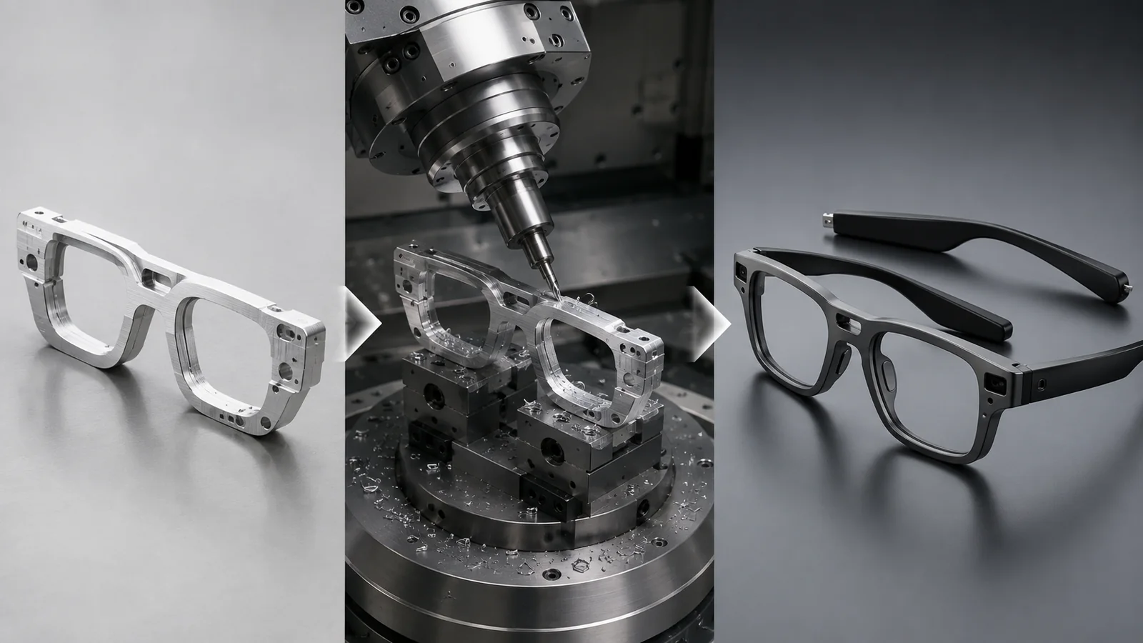
An AI smart-glasses metal front frame requires coordinated control of 5-axis CNC machining, thin-wall free-state geometry, cosmetic toolpaths, anodizing, and assembly with PA plastic temples.
1. Why the front frame is more than a cosmetic component
A conventional eyeglass frame mainly holds lenses and connects the bridge, nose pads and temples. An AI smart-glasses front frame may also support or surround:
- a display or diffractive optical element;
- camera and recording-indicator windows;
- microphone or sensor openings;
- an optical-engine or electronics cavity;
- cable routes and interconnect features;
- interfaces to boards, batteries or communication modules in the temples.
The front frame therefore combines cosmetic, structural and optical-datum functions.
A cosmetic-only control plan may produce a visually acceptable part with incorrect optical position, temple angle or gap and flush. A dimension-only control plan may miss unacceptable tool marks, color mismatch, rack marks or edge feel on a wearable product.
2. Why aluminum and PA work as a multi-material structure
Aluminum and PA normally serve different purposes.
| Material direction | Functions it can support | Main manufacturing risks |
|---|---|---|
| Aluminum-alloy components | Cosmetic surfaces, local stiffness, precision slots, hinge or optical interfaces | Thin-wall distortion, tool marks, dents and anodizing color variation |
| PA plastic components | Complex internal cavities, clips, insulation, lightweight covers and temple shells | Shrinkage, warpage, moisture response, insert stress and long-term creep |
| Metal fasteners or inserts | Repeated opening, screw loading and local load transfer | Loosening, stress concentration and assembly damage |
| Soft nose pads and contact parts | Pressure distribution, grip and comfort | Aging, contamination, size and hardness variation |
The engineering problem is the combination of:
metal precision
+
plastic shrinkage and environmental response
+
low-stress optical assembly
+
deformation during wear
3. Why 5-axis CNC suits a complex eyewear frame
A frame may appear planar, but its features point in many directions and use changing curvature:
- front and rear rim surfaces;
- lens or optical-element grooves;
- bridge transitions;
- side and angled faces;
- hinge seats and screw holes;
- camera or sensor windows;
- inner skin-contact surfaces and edge radii.
Five-axis CNC can provide:
- better access to inner, outer and side features;
- fewer flips and datum transfers;
- more suitable tool orientation on continuous curves;
- better control of the spatial relationship among rims, bridge, windows and hinge seats;
- shorter effective tool overhang in difficult regions;
- more continuous and controllable cosmetic toolpaths.
Five-axis equipment does not automatically create higher accuracy. Machine geometry, rotary-center calibration, fixturing, tool runout, thermal drift, path smoothing and the measurement datum still determine the delivered result.
4. Why multi-style products can favor CNC
AI glasses are expected to resemble ordinary eyewear, which encourages multiple frame shapes, face sizes and decorative versions. Creating a dedicated near-net-shape die for every version can increase development and revision cost.
CNC can offer:
- relatively fast program and fixture adjustment after 3D-model changes;
- partial sharing of stock, tools and inspection logic across frame styles;
- early validation of appearance and fitting dimensions;
- avoidance of committing to many production dies before styles are frozen;
- direct machining of optical and hinge interfaces.
The trade-off is higher material removal, machine time, tooling, fixturing and cosmetic-finishing cost. As demand for one stable frame rises, billet CNC should be compared again with forged or preformed stock, die casting plus machining and other routes.
5. The stock route cannot be identified from the finished appearance
Public information confirms a metal frame and CNC processing, but the finished part alone does not prove whether the starting stock is:
- plate or block;
- forged or preformed stock;
- extrusion;
- die-cast stock;
- another near-net-shape route.
| Stock direction | Main advantages | Main risks |
|---|---|---|
| Plate or block CNC | Flexible change, clear material certification and fast prototype entry | Low material yield and long machining time |
| Forged or preformed stock | Lower material removal and better local material use | Tooling, parting and downstream machining planning |
| Die casting plus CNC | Complex cavities and integrated mounting features | Porosity, appearance, allowance and die-change risk |
| Extrusion | Efficient for long parts with relatively stable cross-sections | Limited suitability for closed rims and multi-directional curves |
The selection should consider style count, design maturity, demand per style, distribution of precision interfaces, cosmetic class and material yield rather than raw-stock price alone.
6. Why a thin front frame distorts
Once the lens-rim openings are cut, the section becomes narrow and closed-loop stiffness falls. The bridge and hinge regions may also contain abrupt section changes.
Common sources include:
- residual stress in the stock;
- unbalanced removal between left and right regions;
- excessive stock removal in one roughing step;
- concentrated fixture pressure;
- poor sequence between inner and outer rim machining;
- removal of temporary links too early;
- unstable cutting force and heat;
- local damage during deburring or pretreatment;
- assembly load from lenses, optical parts or hinges.
A more controlled sequence is:
establish stable stock datums
→ rough in stages
→ retain temporary support or process links
→ release material symmetrically
→ inspect the free state after unclamping
→ semi-finish critical contours
→ finish optical and hinge interfaces
→ complete cosmetic surfaces and remove process links last
Whether intermediate resting, stabilizing treatment or dedicated support is required must be proven for the actual alloy condition, section and frame geometry.
7. A fixture must not force a nonconforming part into conformance
A low-stiffness frame can conform closely to its fixture. If all inspection is performed while clamped, the following failure can remain hidden:
contour is acceptable in the fixture
→ rims open or twist after release
→ lens assembly stress rises
→ temple angle and optical position shift
Fixture DFM should distinguish:
- locating points;
- support points;
- clamping points;
- protected cosmetic surfaces;
- process-link regions;
- 5-axis spindle and tool clearance;
- datum inheritance after refixturing.
Free-state inspection should be included at critical stages. A second check may also be required after lenses or optical parts, hinges and temples are installed because assembly loads can change the frame contour.
8. Machining, optical and assembly datums must connect
Smart glasses contain at least three datum systems.
Machining datums
They control the manufactured relationship among rims, bridge, windows, hinge seats and holes.
Optical datums
They locate the lens, waveguide, display engine, camera or sensor relative to the user’s line of sight.
Assembly datums
They control gap, flush and preload between the front frame, PA temples, nose pads, electronics and covers.
If these datum systems are developed independently, every part report can pass while the finished glasses fail optical, cosmetic or fitting requirements. Drawings and gauges should identify the final functional datum and distinguish it from process-only manufacturing references.
9. Cosmetic toolpaths must be defined in the program
The metal surface entering anodizing retains the history of CNC processing. Consumer-electronics frames require control of:
- final-cut direction on Class-A surfaces;
- tool entry and exit positions;
- symmetry of tool marks between the two rims;
- transitions between planes and curves;
- inner and outer rim edges;
- regions where rework is prohibited;
- burrs around screws, hinges and camera windows;
- evidence left after removing process links;
- dents caused by handling, cleaning and packaging.
Local sanding or polishing may remove a tool mark but create color or gloss variation after anodizing. Rework methods and permitted regions should be approved during master-sample development.
10. Anodizing does not automatically hide machining defects
Anodizing can provide metallic appearance, color and surface protection, but it is not a hiding coating. It can make the following more visible:
- inconsistent toolpath direction;
- local scratches and dents;
- polishing or rework patches;
- color variation among material lots;
- section- or microstructure-related differences;
- uneven pretreatment;
- rack and electrical-contact marks;
- poor masking boundaries;
- texture differences between machined regions.
If a matte finish is required, the specification should state whether the texture comes from CNC, blasting, brushing, chemical pretreatment or a combination. “Matte anodized” alone does not define pretreatment, color, gloss, defect masters or viewing conditions.
11. Dimensional control before and after anodizing
The anodic layer changes the surface condition, while cleaning, pretreatment, masking and racking can affect small bores, grooves, threads and contacts.
The drawing should distinguish:
- cosmetic surfaces that receive the finish;
- lens or optical-element fits;
- hinges and pivot bores;
- threads;
- grounding or conductive contacts;
- bonding surfaces;
- precision locating faces;
- laser-marking or printing zones.
The dimensional stack must be based on the delivered state. Film-sensitive fits require a stated inspection stage, masking rule and pre-anodizing compensation so that customer and supplier do not interpret the same dimension in different conditions.
12. Building a stable aluminum-to-PA assembly
Public information does not disclose the exact joining method. Comparable products may use screws, metal inserts, hinge assemblies, clips, adhesives or combinations.
Multi-material assembly should evaluate:
- PA molding shrinkage versus metal precision;
- moisture and temperature response of the plastic;
- screw preload on thin metal and plastic bosses;
- loosening and wear after repeated hinge cycling;
- left and right temple angle and springback;
- risk of metal edges damaging plastic or wiring;
- flushness between plastic covers and anodized surfaces;
- cosmetic damage during service disassembly;
- thermal-expansion mismatch;
- compatibility with adhesive, cleaning media and perspiration.
A precise metal frame should not be expected to correct large plastic warpage, and excessive screw preload should not be used as the primary method of forcing the assembly to nominal form.
13. Critical CTQs for an AI smart-glasses front frame
| CTQ | Final function | Recommended validation state |
|---|---|---|
| Relative position of the two rims | Optical position and cosmetic symmetry | Free and assembled states |
| Lens or optical-element seating contour | Assembly stress, display performance and retention | After machining, finishing and assembly |
| Bridge and nose-pad position | Wearing height and pressure distribution | Frame and complete product |
| Hinge-axis relationship | Opening feel, temple angle and left-right consistency | Subassembly and complete product |
| Camera or window location | Direction, obstruction and appearance | Optical gauge or complete product |
| Free-state warpage | Prevent false acceptance while clamped | After unclamping |
| Metal-to-plastic gap and flush | Cosmetic and tactile quality | Complete assembly |
| Anodizing color and gloss | Consumer-electronics appearance | Controlled light and master samples |
| Burrs and sharp edges | Wearer feel and assembly safety | Full-perimeter inspection |
| Weight and balance relationship | Extended-wear experience | Complete product |
CTQs should be derived not only from the part drawing but also from optical, electronic, hinge and human-wear failure modes.
14. Inspection cannot rely on one CMM report
A complex frame may require several methods:
- CMM for functional datums, holes and hinge relationships;
- optical or profile measurement for narrow grooves, edges and small windows;
- contour scanning or dedicated gauges for free-state geometry;
- functional gauges for lens or optical-element seats;
- torque and cycling tests for hinges;
- controlled-light inspection and limit samples for color, gloss and appearance;
- complete-product gauges for temple angle, gap, flush and worn geometry;
- assembly trials confirming that the lens or optical part is not over-constrained.
Reports should state the measurement condition. Clamped, free, pre-finish, post-finish and fully assembled data are not interchangeable.
15. From prototype to production
appearance and fitting model
→ CNC engineering prototype
→ verify optical, window and hinge interfaces
→ confirm material and stock route
→ optimize 5-axis program, fixture and tooling
→ validate free and assembled states
→ approve anodizing color and cosmetic limit samples
→ pilot assembly
→ close distortion, toolpath and color issues
→ control production CTQs and traceability
Before production, the team should answer:
- demand per style and total style count;
- whether billet CNC remains the best route;
- which programs, fixtures and gauges can be shared;
- whether cosmetic scrap and material yield are acceptable;
- how anodizing color lots will be controlled;
- how tolerance is divided between PA and metal components;
- which fixtures and finishing tools are affected by design changes;
- which CTQs require capability and trend monitoring.
16. Information required for RFQ
| RFQ input | Engineering purpose |
|---|---|
| Controlled 2D drawings and 3D model | Review style, datum, wall, curves and tool access |
| Alloy and temper | Evaluate machining, distortion and anodizing appearance |
| Required or open stock route | Compare billet, preform and alternative routes |
| Lens and optical assembly relationship | Establish optical datum and fit boundaries |
| Camera, sensor and window locations | Control direction, obstruction and appearance |
| Hinge, temple and nose-pad interfaces | Allocate metal, plastic and assembly tolerance |
| Class-A surfaces and defect limits | Plan toolpaths, handling and finishing |
| Color, gloss and limit masters | Establish anodizing acceptance |
| Rack, masking and conductive regions | Plan finishing fixtures |
| Free-state contour | Prevent fixture-induced false acceptance |
| Complete-product gauge and wearing condition | Verify final assembly function |
| Annual demand, batch size and style count | Evaluate CNC, stock and tooling route |
| Prototype and production timing | Plan programs, fixtures, masters and validation |
Before quotation, the manufacturing team should state:
- which surfaces are functional and which are cosmetic;
- whether 5-axis CNC is solving access, datum integration or both;
- how the free state will be measured after unclamping;
- which dimensions require anodizing compensation or masking;
- how tolerances are divided between aluminum and PA parts;
- whether final acceptance is based on the part, subassembly or worn condition.
Frequently asked questions
Why are metal front frames for AI smart glasses machined on 5-axis CNC equipment?
Five-axis CNC can continuously reach the front, side and inner contours of the lens rims, the bridge and hinge seats while reducing datum transfers caused by repeated flipping. Its main advantages are tool access, fewer setups and continuous cosmetic toolpaths; final accuracy still depends on datums, fixtures, tools, thermal stability and inspection.
How is thin-wall distortion controlled in an aluminum smart-glasses front frame?
Control must combine material condition, feature zoning, rough and finish allowances, balanced material removal, clamping force, temporary support and free-state inspection. A frame should not be accepted only while it is forced flat in a fixture; contour and interface relationships must be rechecked after release and after lenses, hinges and temples are assembled.
Does anodizing hide CNC tool marks on a smart-glasses front frame?
Usually not. Anodizing can make toolpath variation, scratches, rework marks, material-structure differences and uneven pretreatment more visible. Cosmetic toolpaths, roughness, blasting or other pretreatment, rack points, masking, color and gloss masters should therefore be defined jointly during CNC and finishing DFM.
What information is required for an AI smart-glasses aluminum front-frame RFQ?
The RFQ should include controlled 2D drawings, a 3D model, alloy and temper, the expected or open stock route, lens and optical assembly relationships, Class-A cosmetic surfaces, color and gloss masters, anodizing requirements, rack and masking regions, hinge and temple interfaces, free-state contour, complete-product gauge requirements, annual demand, batch size, prototype timing and production timing.
