
In This Article
Direct answer
Die casting plus CNC and billet CNC are not universal substitutes. They use different cost structures and carry different manufacturing risks.
- Billet CNC starts from plate, bar or block. It requires little dedicated tooling, supports rapid design changes and offers a relatively direct material-to-datum chain, but its material use and machining cost rise as the removed volume increases.
- Die casting plus CNC creates a near-net body in a reusable die and machines only the functional interfaces. It can suit complex and stable production parts, but it introduces tooling, die trials, internal discontinuities, trimming, distortion and engineering-change exposure.
The correct comparison covers the complete manufacturing chain:
design maturity
→ production demand
→ stock or tooling
→ casting or billet machining
→ CTQ finishing
→ surface treatment
→ inspection and assembly
→ scrap, rework and engineering changes| Decision condition | More favorable to billet CNC | More favorable to die casting plus CNC |
|---|---|---|
| Design status | Geometry and interfaces are still changing | Geometry and interfaces are frozen |
| Demand | Prototype, low volume or uncertain forecast | Stable medium or high production demand |
| Shape | Open geometry with manageable removal | Curves, ribs, bosses and thin walls |
| Precision scope | Precision is required across many surfaces | CTQs are concentrated in local bores and faces |
| Initial investment | Dedicated tooling should be avoided | Tooling and validation investment is acceptable |
| Unit cycle | Longer machining time is acceptable | Material removal and machining time must be reduced |
| Change risk | Rapid revision is important | Engineering changes are expected to be limited |
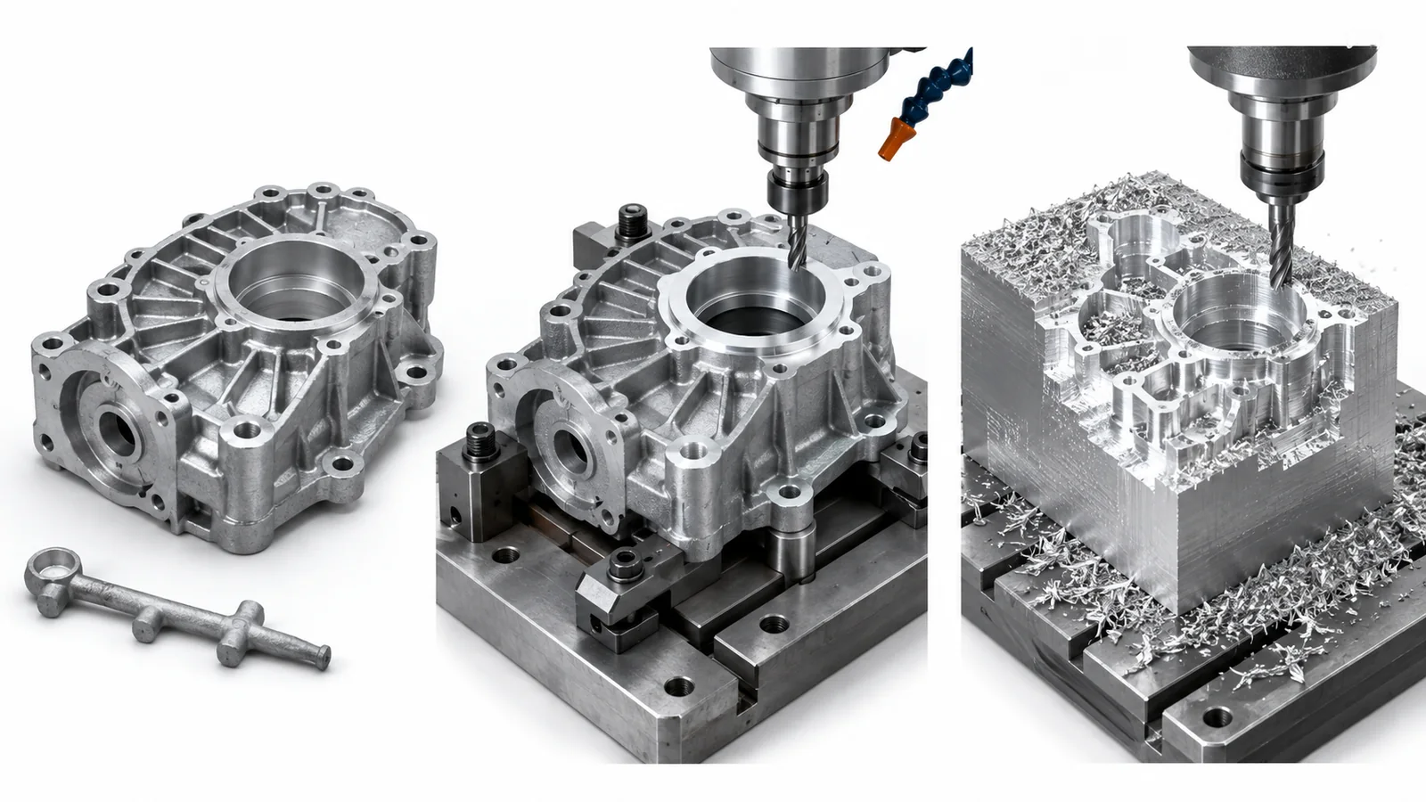
The die-casting route creates the body, ribs, and bosses as a near-net shape before CNC finishes bearing bores, locating diameters, and mounting faces, while billet CNC machines the complete part directly from solid stock.
1. Define the role of die casting in the part
The value of die casting is not to create every final dimension. It is to bring the outer form, cavities, ribs, bosses and transitions close to their finished geometry.
A typical die-cast and machined component contains three groups of features:
| Feature group | Preferred manufacturing route | Reason |
|---|---|---|
| Body shape, thin walls and curves | Near-net die casting | Reduces raw material and contour machining |
| Ribs and noncritical bosses | Die casting | Integrates structure and reduces part count |
| Bearing bores and locating diameters | CNC machining | Requires controlled datums, size and surface quality |
| Threads, dowel holes and precise hole patterns | CNC machining | Requires controlled form and positional relationships |
| Noncritical chamfers and cosmetic transitions | Casting or trimming | Depends on appearance, parting and finishing |
The practical division is:
die casting creates shape and integration
+
CNC creates functional interfaces
+
inspection proves the relationship between them
2. When billet CNC is the stronger route
The principal benefits of billet CNC are flexibility and process transparency, not necessarily the lowest raw-material price.
Billet CNC is often more suitable when:
- the part is a concept or engineering prototype;
- the drawing is still changing;
- annual demand is low or uncertain;
- bearing, sealing and mounting surfaces cover a large share of the part;
- material condition and internal continuity are critical;
- geometry is open and tool access is straightforward;
- several versions must be tested in a short development window;
- die casting would still be followed by extensive machining.
Main advantages of billet CNC
- No production die is required.
- Geometry, hole positions and wall thicknesses can be revised quickly.
- Process datums can be established directly from the stock.
- Casting porosity is not introduced.
- Low quantities do not carry die-trial and tooling amortization.
- Material specification and certification can be directly tied to the stock.
Main limitations of billet CNC
- large cavities create substantial material loss;
- roughing consumes machine capacity;
- deep pockets and thin walls increase vibration and distortion;
- complex forms may require multi-axis equipment and several setups;
- unit cost has limited reduction as demand grows;
- chips, tooling and machine hours become the dominant cost drivers.
Billet CNC is strongest when the project values rapid, controlled change more than mature high-volume efficiency.
3. When die casting plus CNC becomes attractive
Once the product architecture is stable, die casting can integrate complex geometry and noncritical mounting structures into one near-net blank.
Stronger candidates often include:
- curved or enclosed external geometry;
- multiple ribs, bosses and local pads;
- high material removal from billet;
- a relatively large overall envelope with localized CTQs;
- stable production demand and product life;
- a need to reduce CNC cycle time;
- opportunities to replace several brackets or joined pieces;
- low probability of major geometry revision.
The benefit comes from near-net shaping and functional integration. If a casting still requires broad remachining of the exterior or removal of thick, nonfunctional stock, the design has not captured the economic purpose of die casting.
4. Compare three layers of cost
A low casting price does not by itself prove that die casting is the lower-cost route. A complete comparison includes three cost layers.
4.1 Upfront investment
- product and die-casting DFM;
- die design and manufacture;
- filling and solidification evaluation;
- die trials and samples;
- die correction and dimensional compensation;
- trim tooling, CNC fixtures and gauges;
- finishing and assembly validation.
4.2 Unit manufacturing cost
- alloy and melting;
- machine cycle and die operation;
- gate removal, trimming and cleaning;
- CNC machining;
- tooling, fixtures and inspection;
- surface treatment;
- scrap, rework and sorting;
- packaging and lot traceability.
4.3 Life-cycle cost
- die changes after engineering revisions;
- die maintenance and service life;
- capacity transfer and supply interruption;
- downstream loss caused by hidden internal defects;
- production variation;
- spare die and downtime exposure;
- unrecovered tooling at product end of life.
There is no universal production quantity at which every part should switch to die casting. The economic threshold is an engineering estimate based on:
tooling and validation investment
÷
per-part material, machining and assembly savings
Scrap, engineering-change probability and cash commitment must also be included.
5. Complete die-casting DFM before tool release
A billet-machined drawing cannot simply be transferred to a die maker with draft added.
The DFM review should define:
- parting-line location;
- ejection direction and draft;
- gate, overflow and vent regions;
- wall thickness and transitions;
- ribs, radii and bosses;
- ejector locations;
- slides or cores;
- downstream CNC datums;
- internal quality in critical machining zones;
- machining allowance and its direction;
- trimming and gate-removal method;
- finishing and cosmetic boundaries.
Uniform walls, suitable radii and sufficient draft support filling, ejection and repeatability. The parting line must also be selected early because it affects gates, vents, flash, trimming, appearance and later locating.
6. Features that should remain CNC operations
Die casting can achieve useful structural accuracy, but the following features commonly remain CNC and inspection priorities:
- bearing bores;
- motor, reducer or encoder locating diameters;
- precision dowel holes;
- critical threads and tap-drill depths;
- sealing grooves and faces;
- high-flatness mounting planes;
- thermal contact surfaces;
- position-controlled hole patterns;
- sliding or contact surfaces with defined roughness;
- functional datums that control an assembly stack.
CNC is not a repair step for uncontrolled casting. If internal quality, casting datums or allowance are unstable, precision machining cannot automatically convert every blank into a conforming part.
7. Machining allowance is not safer simply because it is larger
Insufficient allowance can cause:
- incomplete cleanup;
- remaining mismatch or distortion;
- exposed as-cast defects;
- incomplete functional surfaces.
Excessive allowance can cause:
- longer machining time;
- exposure of deeper porosity or shrinkage;
- loss of local stiffness;
- residual-stress redistribution;
- thin-wall and bore distortion;
- loss of near-net-shape cost benefit.
Allowance should therefore be assigned by feature. The drawing and process plan should identify the casting datum, allowance direction and whether die wear and lot variation remain covered.
8. Why porosity appears during CNC machining
High-speed filling, trapped gas and local solidification behavior can create gas- or shrinkage-related discontinuities below the surface. A visually acceptable blank may still contain a defect in a critical machining zone.
A typical failure chain is:
cast surface appears acceptable
→ CNC opens a bearing bore, thread or sealing face
→ internal porosity becomes exposed
→ continuity, strength or sealing performance is lost
High-risk regions should therefore be kept away from:
- bearing bore walls;
- highly loaded threads;
- sealing grooves;
- thin-wall roots;
- high-stress fillets;
- large thermal contact faces;
- later welding or high-temperature treatment zones.
Parts with pressure, sealing or structural-integrity requirements need a risk-based validation plan. Depending on the application, this may include radiography, CT, sectioning, density checks, leak testing, pressure testing or monitored process parameters. Acceptance criteria must follow functional risk rather than assume that any discontinuity is acceptable because the part is cast.
9. Why a casting can distort after machining
Distortion can originate in both the casting and CNC stages.
9.1 Casting-stage contributors
- nonuniform walls and cooling;
- ejection while the part remains too hot;
- poor ejector or handling locations;
- local heavy sections;
- parting mismatch;
- die-temperature or spray variation;
- stress release during trimming.
9.2 CNC-stage contributors
- forcing a warped blank flat in the fixture;
- removing stock primarily from one side;
- reducing support around thin walls;
- unstable cutting load or heat;
- repeated datum changes;
- failing to check the free state before finishing;
- dimensional change after surface treatment.
Fixtures should not merely force the blank into nominal geometry. The process should create repeatable cast locating zones, separate locating from clamping, and include free-state checks where distortion can affect CTQs.
10. Inspection must cover the blank, machining and function
| Stage | Main checks | Purpose |
|---|---|---|
| Alloy and melt records | Material identity and lot history | Maintain traceability |
| Die-casting process | Key parameters, die temperature and cycle state | Detect process drift |
| Blank appearance | Fill, cold shuts, cracks, flash and ejector marks | Remove obvious defects |
| Blank dimensions | Locating zones, stock and distortion | Confirm CNC readiness |
| Internal quality | Risk-based nondestructive or destructive checks | Validate critical machining zones |
| CNC process | First article, tool offsets, bores, faces and stock trend | Control CTQs |
| After finishing | Coating, appearance and critical dimensions | Detect secondary-process effects |
| Functional validation | Assembly, torque, leakage, pressure or contact | Prove final use |
A final CMM report alone cannot prove casting integrity, sealing performance or long-term function.
11. Finishing can amplify differences between cast and machined surfaces
The as-cast surface, trimmed regions and machined surfaces have different texture and surface condition. Conversion coating, paint, plating or other finishes may reveal:
- gloss and texture differences;
- color variation;
- amplified surface discontinuities;
- local treatment anomalies at pores;
- visible machining boundaries;
- adhesion loss from inadequate cleaning;
- dimensional or electrical changes caused by masking.
Class-A cosmetic surfaces, electrical contacts, thermal interfaces, sealing faces and finishing boundaries should be defined during DFM. The finishing process should not be expected to hide uncontrolled casting and machining differences after the part is complete.
12. Switching from a CNC prototype to die-cast production requires a new process
A typical transition is:
billet CNC prototype
→ verify form, fit and function
→ die-casting DFM and tool design
→ tool trial
→ blank and internal-quality validation
→ rebuild CNC datums and allowance
→ finishing and assembly validation
→ pilot production confirmation
→ stable production
The transition must revalidate:
- any alloy-system change;
- wall thickness and radii redesigned for casting;
- blank locating strategy;
- CTQ machining sequence;
- casting shrinkage and machining compensation;
- porosity and shrinkage acceptance;
- finishing appearance;
- assembly preload and stiffness;
- production capability.
A conforming billet prototype only proves that the design works in that material and process. It does not prove that a die-cast production route will produce the same result.
13. Application examples
Humanoid robot housings and brackets
A housing with complex outer geometry, ribs and several noncritical mounting structures may be a candidate for die casting plus CNC when bearing bores, locating diameters and mounting faces are localized. Highly loaded actuator housings still require careful material, internal-quality and fatigue-zone validation.
Optical-transceiver and electronic structures
Complex housings, shielding geometry and bosses may benefit from die-cast integration. Thermal contact faces, optical datums, connector bores and cosmetic surfaces commonly remain machining or finishing priorities. High heat-flux parts also require confirmation that alloy and internal discontinuities do not compromise the thermal path.
General motor, instrument and equipment housings
End covers, brackets and protective housings are common candidates. Stable demand, complex shape and localized CTQs favor die casting. Numerous versions, low volumes or precision across most surfaces favor billet CNC.
14. Information required for RFQ evaluation
| RFQ input | Why it matters |
|---|---|
| 2D drawing and 3D model | Review parting, ejection, wall thickness and machining zones |
| Annual and batch volume | Evaluate tooling amortization and capacity |
| Design-freeze status | Estimate tool-change exposure |
| Material and standard | Define casting or billet system |
| CTQs and assembly relationships | Split casting and CNC responsibilities |
| Leakage, pressure and load | Define internal quality and validation |
| Finish and cosmetic class | Plan cast, machined and masked surfaces |
| Allowed discontinuities and inspection | Establish casting acceptance boundaries |
| Prototype and production timing | Plan the transition from billet to tooling |
| Reports and traceability | Define material, lot, process and inspection records |
Before quotation, the supplier should be able to state:
- which shapes will be formed by casting;
- which functions will be guaranteed by CNC;
- which risks will be verified by inspection;
- which changes will affect tooling and timing;
- where the expected cost advantage comes from.
Frequently asked questions
How should a buyer choose between die casting plus CNC and billet CNC?
The decision should combine design maturity, annual and batch volume, geometric complexity, material removal, functional CTQs, tooling budget and engineering-change risk. Prototypes and low volumes generally favor billet CNC, while stable production parts that gain substantial material and machine-time savings from near-net shaping are stronger candidates for die casting plus CNC.
Why do die-cast parts still need CNC machining on critical bores and mounting faces?
Die casting is effective for complex shapes, thin walls, ribs and bosses, but bearing bores, locating diameters, threads, sealing faces and high-flatness mounting surfaces usually need more stable datums, dimensions and surface quality. These features should therefore be completed and inspected after casting by CNC machining.
What are the main quality risks in a die-cast part?
Major risks include gas porosity, shrinkage porosity, cold shuts, incomplete fill, ejection distortion, parting-line variation and inconsistent machining stock. CNC may expose defects that were hidden below the cast surface, so critical machining zones, internal quality, allowance and inspection must be planned together during die-casting DFM.
What information is required for a die-casting RFQ?
The RFQ should include 2D drawings, a 3D model, material and finishing requirements, annual and batch volume, functional CTQs, assembly relationships, pressure or sealing requirements, cosmetic classes, acceptable casting discontinuities, inspection reports, prototype plans, production timing and the current design-freeze status.
