
In This Article
Direct answer
Anodizing color variation is not a problem created by the final dye step alone. The delivered appearance results from a complete manufacturing chain:
alloy and material lot
→ CNC, brushing, polishing, blasting or chemical matting
→ anodic film formation
→ dye uptake
→ racking and production load
→ rinsing and sealing
→ color, gloss and texture inspection
A change in any step can appear as:
- shade differences within one batch;
- different regions on one part;
- a prototype that does not match production;
- the same color name looking different between suppliers;
- color becoming lighter after sealing;
- similar hue but different gloss or texture.
Color should be treated as a CTQ with tolerance, not as an absolute text label.
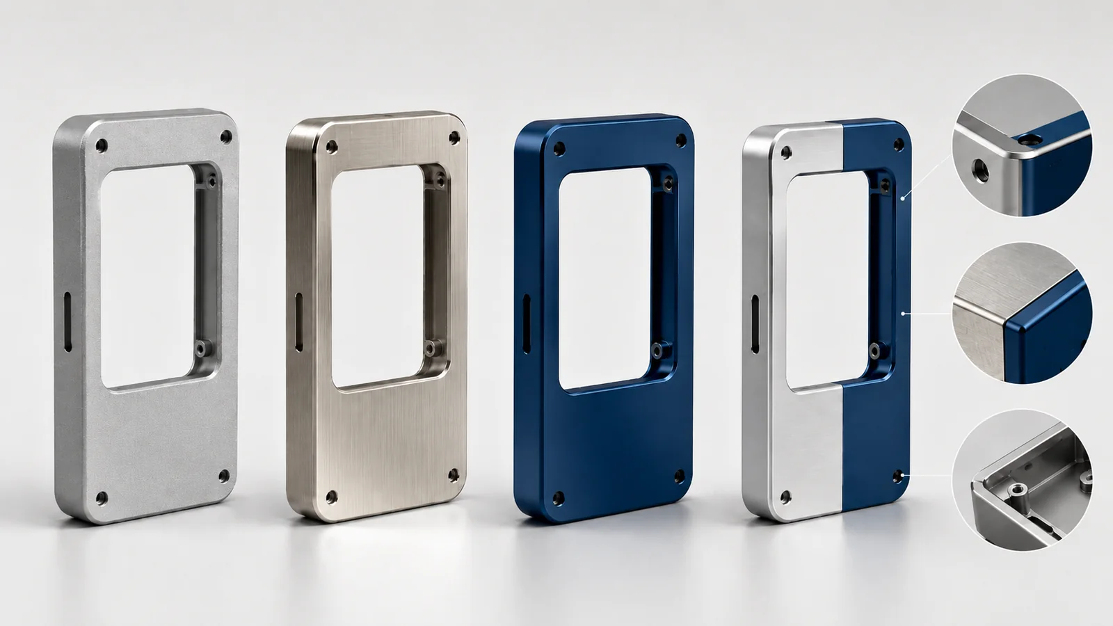
Final anodized appearance depends not only on the dye, but also on the substrate tone, machining texture, blasting condition, anodic film and sealing process.
1. Why dye alone does not explain color variation
Color anodizing generally forms a porous oxide film, introduces dye into the film and then seals the surface.
Final color is influenced by at least four groups:
| Group | Main influence |
|---|---|
| Aluminum substrate | Natural film color, dyeing response and base tone |
| Anodic film | Dye-receiving structure, thickness and uniformity |
| Dye process | Dye type, concentration, temperature, time and condition |
| Product and rack | Base finish, geometry, position, load and immersion timing |
An unchanged dye formula cannot guarantee identical color on every material, surface or load.
2. Why the same alloy designation may still look different
An alloy designation defines major chemistry, but production appearance can still be influenced by:
- material supplier;
- production lot;
- plate, extrusion, forging or casting stock;
- temper and heat-treatment condition;
- microstructural uniformity;
- surface versus core condition;
- machined areas versus original stock surfaces.
Industrial finishing guidance also notes that natural anodized color can vary with material source. For adjacent cosmetic parts, the preferred approach is:
same alloy
+
same supply condition
+
preferably the same material lot
+
the same anodizing batch
The same grade is necessary, but may not be sufficient for a visually exact match.
3. Why different alloys are difficult to match exactly
Different aluminum alloys contain different alloying elements and develop different natural oxide colors, pore conditions and dyeing responses.
Published processing examples show that under the same anodizing and dye time, some 2000- or 7000-series materials may dye faster and darker than a 5000-series alloy. Their oxide films may also contribute a yellowish tone. Cast and die-cast aluminum can form darker gray or brown base colors.
The final result is closer to:
substrate and oxide base tone
+
dye color
=
visible final color
Two adjacent parts made from different alloys may be adjusted to a similar depth, but exact hue, gloss and angular appearance remain difficult to match.
4. Why the base finish changes perceived color
One part may include:
- original stock surface;
- CNC milled surface;
- turned surface;
- EDM surface;
- brushed surface;
- polished surface;
- blasted surface;
- chemically matted surface;
- locally hand-finished surface.
These surfaces reflect light differently. After anodizing, similar film and dye conditions can still appear as different brightness, gloss and color.
Local hand repair on a class-A face is especially risky because it can change:
- tool-mark direction;
- roughness;
- local reflection;
- pretreatment response;
- visible shade boundaries.
Cosmetic parts therefore require an approved repair method rather than uncontrolled polishing after machining.
5. Why CNC toolpaths can remain visible after anodizing
Anodizing does not automatically fill or erase CNC tool marks. A clear or colored oxide film preserves and may emphasize base reflection.
Typical causes of visible variation include:
- different tools on one face;
- new and worn cutters producing different surfaces;
- toolpath direction changes;
- blend lines between passes;
- local recutting;
- chatter on thin walls;
- deburring that touches a cosmetic face.
For a visible machined finish, standardize:
- tool type;
- tool-life window;
- final path direction;
- stepover;
- blend location;
- repair rules.
For parts that will be blasted, deep tool marks, chatter and local handwork may still remain visible as clouds or reflection differences after anodizing.
6. How blasting and chemical matting influence color
Blasting creates diffuse reflection by changing microtexture. Chemical matting or etching changes the surface by chemical removal.
Both affect:
- brightness;
- matte level;
- perceived saturation;
- angular appearance;
- edge definition;
- substrate removal before anodizing.
Production blasting should control:
- media;
- particle size;
- pressure;
- distance;
- angle;
- time;
- sequence;
- media life;
- the boundary between class-A and non-cosmetic surfaces.
A blasted surface and an original stock surface can look like two colors even when both receive the same dye. Visible regions should therefore use a consistent base finish.
7. How anodizing solution, temperature and film thickness affect dyeing
Dye enters the anodic film, so the state of that film affects color.
Industrial processing guidance identifies these as important variables:
- anodizing solution condition and concentration;
- solution temperature;
- film thickness;
- current density;
- treatment load.
These conditions influence film formation and dye uptake. Controlling only the dye bath is not sufficient.
A thinner film may provide less effective depth for dye and appear lighter. A thicker film may increase dye capacity, but thickness must still satisfy:
- drawing requirement;
- dimensional tolerance;
- wear and corrosion performance;
- edge condition;
- dyeing and sealing stability.
8. Why dye concentration, temperature and time must be controlled together
Shade cannot be managed by time alone.
The dye process should control:
- dye type;
- dye identification or color family;
- concentration;
- temperature;
- pH or supplier-specified bath condition;
- dye time;
- circulation;
- age, contamination and maintenance.
A strong dye used with a very short immersion may look convenient for a pale shade, but it magnifies entry-time differences, restricted flow in complex geometry and rack-position effects.
For pale or champagne tones that are sensitive to seconds of variation, a repeatable concentration-and-time window is more robust than relying on rapid manual immersion.
9. Why rack position can create variation within one load
One rack may carry many parts. During entry, different heights and positions do not contact the dye at exactly the same moment. A similar timing difference occurs during withdrawal.
When total dye time is short, a difference of seconds can become a large percentage of the process and cause:
- top-to-bottom shade variation;
- front-to-back rack variation;
- internal-to-external variation on complex parts;
- differences between the first and last positions.
Production should standardize:
- rack orientation;
- parts per rack;
- spacing;
- vertical position;
- immersion and withdrawal method;
- definition of effective dye time;
- rack strategy for sensitive pale colors.
10. Why a prototype color may not reproduce in production
A prototype may include one or a few parts. Production may fill an entire rack.
The change in quantity can alter:
- total electrical load;
- effective current density;
- solution flow;
- temperature recovery;
- electrical contact;
- immersion timing;
- local dye exchange.
Industrial guidance recommends using suitable dummy material or simulated load during prototyping to approximate production conditions.
A robust route is:
single-part condition trial
→ simulated production-load trial
→ pilot full-rack validation
→ production
A single attractive prototype does not prove a stable mass-production color.
11. Why sealing can change color again
Color at the end of dyeing is not necessarily the final delivered color. Rinsing and sealing can change it.
Depending on dye and film condition, sealing may cause:
- lighter shade;
- slight hue shift;
- gloss change;
- dye loss;
- variation from residue or contamination.
Color should therefore be approved after the specified rinsing, sealing, drying and conditioning, not immediately after the dye bath.
A prototype made by one supplier may also be difficult for another supplier to reproduce because the dye family and sealing route may differ.
12. Why a color name does not define one exact color
Names such as blue, red, black and champagne only define a broad direction.
Actual appearance depends on:
- dye brand;
- dye identification;
- concentration;
- natural film tone;
- base gloss;
- dye depth;
- sealing shift;
- lighting and viewing angle.
Two suppliers that both specify blue anodizing may not use the same dye or process window.
An RFQ should not stop at:
blue anodizingIt should add:
approved physical sample
+
permitted light and dark limits
+
viewing condition
+
material and base-finish definition
13. Why color needs tolerance and limit samples
Machined dimensions have tolerances. Anodized color also needs an acceptable range.
A useful sample set can include:
- target sample;
- acceptable light limit;
- acceptable dark limit;
- upper gloss limit;
- lower gloss limit;
- unacceptable mottling example;
- acceptable rack mark and edge condition.
This helps the customer, machining supplier and finishing supplier judge the same standard.
For highly visible products, define:
- light source;
- color temperature;
- viewing distance;
- viewing angle;
- observation time;
- whether rotation is allowed;
- whether adjacent assembled parts are compared.
14. Different control priorities for black, pale and natural finishes
Black and dark colors
Dark colors may hide minor hue differences, but can still reveal:
- film variation;
- gray patches;
- different base gloss;
- chemical residue;
- uneven sealing;
- insufficient dye in deep or complex regions.
Pale and champagne colors
Shorter dye times can make pale colors more sensitive to immersion timing, concentration and rack position. Small substrate-tone differences also have a stronger influence.
Natural or clear anodizing
Without dye coverage, alloy chemistry, natural film color, base finish and pretreatment are directly visible.
No dye does not mean no color-control difficulty.
15. Why stripping and rework are risky
When color variation occurs, stripping and redyeing may appear to be the obvious response. However, repeated stripping and pretreatment can continue to change:
- substrate dimensions;
- edges;
- roughness;
- CNC texture;
- blasted condition;
- threads and mating faces;
- the color of the second anodizing cycle.
Rework may improve the match or create new dimensional and cosmetic problems. Before rework, evaluate:
- available dimensional allowance;
- whether the class-A texture may change;
- effect on threads and precision bores;
- whether substrate tone has already shifted;
- approved rework count;
- inspection after rework.
Prevention is usually more reliable than stripping after failure.
16. Freezing the color window from prototype to production
standardize alloy and supply condition
→ freeze CNC base and repair rules
→ freeze blasting or brushing parameters
→ select anodic film and dye system
→ make multi-level color samples
→ validate final color after sealing
→ simulate production load
→ freeze rack and parts per rack
→ confirm pilot lot
→ establish limit samples and lot traceability
Recommended records include:
- material lot;
- stock form;
- CNC tool and final toolpath;
- blasting parameters;
- local repair;
- rack ID;
- part count and position;
- anodizing bath condition;
- film thickness;
- dye identification, concentration and time;
- sealing condition;
- final visual decision;
- rework history.
17. RFQ information
| RFQ input | Engineering use |
|---|---|
| Alloy and temper | Assess natural film tone and dye response |
| Material-lot requirement | Control adjacent-part consistency |
| Controlled 2D drawing and 3D model | Identify complex regions, rack points and class-A surfaces |
| CNC base-finish requirement | Control tool marks, polish and repair |
| Blasting or brushing specification | Control reflection and direction |
| Target color and gloss | Define appearance |
| Physical sample with limits | Create executable color tolerance |
| Film and sealing requirement | Control function and final shade |
| Rack restrictions | Keep contact marks away from class-A surfaces |
| Critical dimensional state | Evaluate anodizing and rework risk |
| Prototype quantity and production lot | Design simulated load and rack |
| Annual demand and delivery frequency | Plan dye maintenance and lot control |
Before quotation, confirm:
- whether adjacent parts require the same material and anodizing batch;
- whether color is controlled by text, color card or physical sample;
- acceptable light, dark and gloss limits;
- whether one class-A face includes multiple base finishes;
- whether prototype racking must simulate production;
- whether stripping and rework are permitted.
Frequently asked questions
Why can the same aluminum alloy and anodizing color still show variation?
The same alloy designation can still include variation in material lot, supply condition, microstructure and machined base surface. Film thickness, dye condition, rack position, production load and sealing also influence final color. Consistency must therefore be controlled from material through sealing, not by dye time alone.
Why do CNC tool marks and blasting affect anodized color?
Machined, brushed, polished, blasted and chemically matted surfaces reflect light differently, so anodizing can reveal different brightness, gloss and perceived color. Even with similar dye conditions, multiple base finishes on one visible part can appear as multiple colors.
Can anodizing color variation always be corrected by rework?
Complete correction cannot be assumed. Stripping and repeated pretreatment continue to change the substrate surface, dimensions, edges and reflection, and redyeing may not restore the original appearance. Prevention through material, base finish, racking, film, dye and sealing control is preferred, with dimensional and cosmetic risk reviewed before rework.
What information is required in an RFQ for color-anodized aluminum parts?
Provide alloy and temper, material-lot requirements, controlled 2D drawings and 3D model, base-finish specification, blasting or brushing direction, target color and gloss, allowable color variation, class-A surfaces, rack restrictions, film thickness, sealing, critical dimensional state, physical samples, prototype quantity, production lot and annual demand.
