
In This Article
Direct answer
Anodizing is not a simple fixed-thickness addition to a CNC aluminum part. Final dimensions are influenced by at least three effects:
CNC substrate dimension
− substrate removed by pretreatment
+ outward oxide growth
= final dimension after anodizing
The oxide develops within the aluminum while also growing outward, so the full nominal film thickness cannot be treated like a plated buildup. Public industrial guidance often uses an approximate half-inward and half-outward model for initial estimates, but actual growth, pretreatment removal, thickness variation and geometry effects must be confirmed for the material and supplier process.
For tight tolerances, there are three practical control routes:
- compensate the CNC target before anodizing;
- mask the functional region;
- anodize first and finish-machine the critical feature afterward.
Masking does not guarantee a perfectly oxide-free boundary. Electrolyte leakage, fixture wear and boundary variation can still create local film. Post-anodize machining provides a direct final dimension, but removes local oxide continuity.
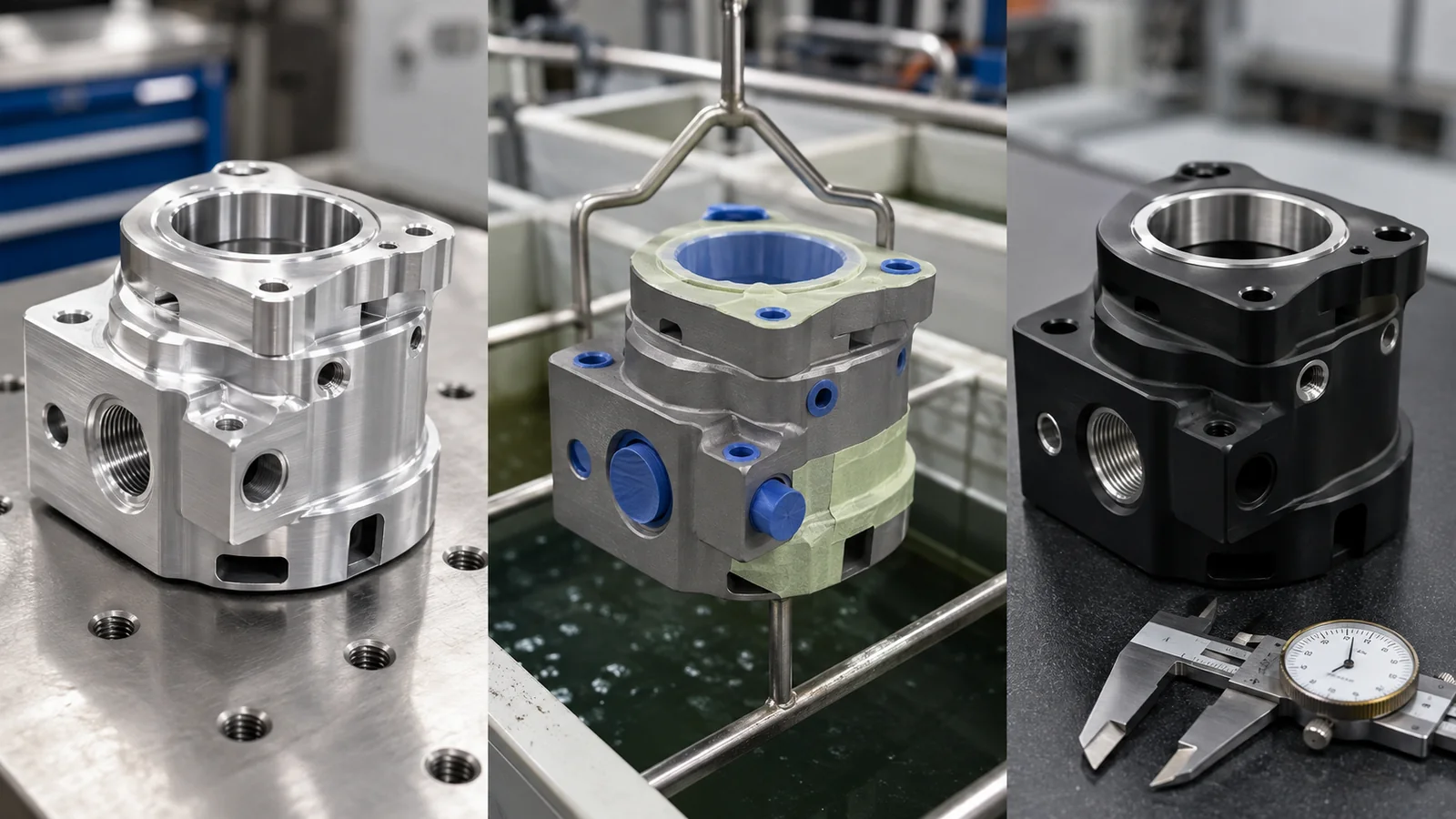
Before anodizing, bores, threads, locating surfaces and sealing faces should be classified for machining compensation, local masking or post-anodize finishing.
1. Why film thickness alone does not define dimensional change
With conventional plating, a simple mental model is that the deposited thickness builds above the substrate.
Anodizing is different. During oxide formation:
- part of the film forms within the original substrate region;
- part grows outward from the original surface;
- pretreatment may dissolve aluminum before film formation;
- current density, flow, geometry and electrical contact affect local behavior;
- sealing changes the film condition but should not be treated as a simple mechanical compensation.
Outside diameters, bores, grooves and walls therefore require separate assessment.
| Feature | Typical dimensional tendency | Engineering interpretation |
|---|---|---|
| Outside diameter | May increase | Net result of outward growth and pretreatment removal |
| Bore | May decrease | Opposing walls grow into the bore, while pretreatment may enlarge it first |
| Groove width | May decrease | Both sidewalls grow into the groove |
| Wall thickness | Net change may be small but relevant | Both faces are affected by pretreatment and growth |
| Thread | Pitch diameter, flanks and assembly feel change | Small and fine threads are more sensitive |
| Roughness | May change | Pretreatment, oxide and sealing all contribute |
2. Why pretreatment belongs in the tolerance stack
An anodizing route commonly includes cleaning, degreasing, etching, desmutting, chemical matting or other preparation. Ignoring pretreatment and calculating only oxide growth is a common cause of fit failure.
Published industrial examples show that etching dissolves aluminum and that chemical matting can create additional dimensional loss. The numerical removal values in those examples are supplier-specific and must not be copied as universal values. The transferable lesson is:
Final size is the net result of substrate removal followed by oxide formation.
The RFQ and sample plan should confirm:
- whether alkaline etching is used;
- whether chemical matting is used;
- whether blasting or mechanical brushing is required;
- whether pretreatment is driven by appearance or dimension;
- how substrate removal is verified;
- whether stripping and reprocessing are permitted;
- how repeated processing affects size and appearance.
3. The half-outward model is only an initial estimate
Industry explanations commonly describe an approximate 1:1 relationship between inward formation and outward growth. With a nominal 30 micrometre film, an initial estimate may use about 15 micrometres of outward growth per surface. In that simplified model:
- an outside diameter may increase by about 30 micrometres;
- a bore may decrease by about 30 micrometres;
- a groove coated on both sides may narrow by about 30 micrometres.
This is only a starting model. Actual results can differ because:
- film thickness is a range rather than a single value;
- pretreatment changes the substrate first;
- deep holes, narrow grooves, corners and rack regions may not coat uniformly.
A drawing should not merely state a film thickness and leave the pre-anodize target undefined.
4. What a published fit calculation demonstrates
One published case uses a final bore of diameter 50 H8 with hard anodizing at 30 plus or minus 5 micrometres and an approximate half-outward model. To keep the finished bore inside its final tolerance, the bore must be machined larger before anodizing and the film tolerance must be included.
The case derives an approximate pre-anodize bore range of:
50.035 mm to 50.064 mmThe lesson is more important than the number:
- a final tolerance span of 0.039 mm does not mean CNC still has the full 0.039 mm process window;
- film variation consumes part of that window, so the pre-anodize machining process may need tighter control.
The range applies only to that example. Every project must recalculate from its own final tolerance, film range and validated supplier data.
5. Selecting among three dimensional-control routes
Industrial guidance groups dimensional control into three basic routes: compensated machining, masking and post-anodize machining.
| Route | Suitable conditions | Advantages | Main risks |
|---|---|---|---|
| CNC compensation | Stable film, open geometry, oxide acceptable on feature | Continuous surface protection and no added machining step | Requires reliable process data and can compress the machining window |
| Local masking | Electrical, sealing, thread or close-fit region | Retains substrate condition and limits oxide effect | Tooling, labor, leakage and boundary variation |
| Post-anodize machining | Extremely tight dimensions, critical sealing or precise locating | Direct control of delivered size | Local oxide removal, added fixturing, cleaning and protection |
Routes can be combined:
anodize most surfaces
+
mask threaded holes
+
finish-bore the bearing seat after anodizing
+
mask the electrical contact
6. Common masking methods
Silicone plugs, sleeves and dedicated silicone tools
Useful for:
- through holes;
- threaded holes;
- dowel holes;
- local sealing grooves;
- regular fit regions.
Standard plugs can work for common bores. Faces, unusual grooves and complex boundaries often require dedicated tools, which increases cost for one-off or multi-version parts.
Masking coating
Useful for:
- curved surfaces;
- irregular regions;
- one-off samples where standard plugs do not fit;
- designs that are still changing.
It offers flexibility but depends on manual application. Labor, edge repeatability and residue removal need control.
Masking requirements should define:
- masked region;
- boundary tolerance;
- allowable oxide intrusion;
- cleaning after mask removal;
- whether cosmetic witness marks are acceptable;
- dedicated tooling and maintenance requirements.
7. Why masking cannot guarantee zero oxide
Even with plugs or dedicated masks, the process can still experience:
- electrolyte leakage at the edge;
- inconsistent plug compression;
- irregular film at the bore entrance;
- fixture wear;
- degradation from chemistry, temperature and reuse;
- edge damage when the mask is removed;
- local oxide reaching a thread root or sealing groove.
Masking reduces oxide exposure but should not be treated as an absolute zero-film guarantee without validation.
8. Features that often favor masking or post-machining
| Functional region | Typical risk | Preferred evaluation |
|---|---|---|
| Bearing bore | Size, roundness and roughness change | Post-machining or validated compensation |
| Locating diameter | Tight fit and concentricity change | Masking or post-machining |
| Precision dowel hole | Size and locating function loss | Post-reaming or masking |
| Thread | Gauge failure and unstable torque | Masking, compensation or post-tapping |
| Sealing face and groove | Form, roughness and film boundary change | Masking or post-machining |
| Electrical ground | Oxide causes insulation | Explicit masking or oxide removal |
| Bonding surface | Surface chemistry affects adhesion | Define with the adhesive system |
| Thermal interface | Contact resistance and flatness change | Masking or post-finishing |
| Class-A cosmetic face | Rack mark and masking boundary | Keep contact and mask boundaries away |
9. Thread treatment options
Threads should not be universally specified as fully coated or fully masked.
Allow full anodizing
Suitable when:
- tolerance is relatively open;
- corrosion or wear protection is more important;
- thread compensation has been validated;
- assembly torque has sufficient margin.
Mask the thread
Suitable when:
- conductivity or grounding is required;
- the thread is small or fine;
- oxide would cause binding;
- the assembly cannot tolerate film.
Risks include incomplete sealing, residual oxide at the entrance and variable mask boundaries.
Tap or chase after anodizing
Suitable when:
- the final gauge result must be directly guaranteed;
- local oxide removal is acceptable;
- chips, cleaning and edge protection can be controlled.
Thread chasing removes oxide from the flanks and can create burrs, chips and cosmetic differences. The drawing and process plan must state whether it is permitted.
10. Defining dimensional condition on the drawing
Requirements should be divided into four layers.
Final functional dimensions
Inspect after anodizing, sealing and all downstream operations.
Pre-anodize machining targets
Define in the process plan or as auxiliary drawing dimensions for CNC compensation.
Film and pretreatment requirements
Specify anodize type, thickness range, color, sealing, matting or blasting.
Local exceptions
Identify masking, electrical contacts, post-machining, no-film regions and allowed oxide intrusion.
A practical drawing note is:
Unless otherwise specified, dimensions apply to the final condition after anodizing and sealing.
Critical bores, threads, sealing faces and conductive regions follow local callouts.
Pre-anodize machining compensation is controlled by the approved process plan.
11. What the anodizing supplier can directly control
An important process boundary is that the anodizing operation directly controls film thickness and process conditions. Final mechanical size also depends on pre-anodize machining, pretreatment removal and any downstream finishing.
For tight dimensions, define:
- who calculates the pre-anodize target;
- who confirms film and pretreatment data;
- who owns masking tooling;
- who measures before anodizing;
- who measures after anodizing;
- whether stripping and rework are allowed;
- rework limits and cosmetic risk;
- the final responsibility boundary.
12. Inspection before and after anodizing
| Stage | Main checks | Purpose |
|---|---|---|
| CNC first article | Pre-anodize target, datums and stock | Confirm compensation logic |
| CNC production | Bore, groove, thread and critical-face trend | Prevent a wrong batch entering finishing |
| Anodizing process | Film, pretreatment, rack and masking | Control finishing consistency |
| Post-anodize dimension | Final bores, diameters, grooves and locators | Prove delivered size |
| Post-anodize function | Thread gauges, fit gauges, conductivity and sealing | Prove assembly function |
| Cosmetic inspection | Color, gloss, rack mark and boundary | Prove appearance |
| Assembly validation | Real fits and stack behavior | Prevent part-level pass and assembly failure |
Small, deep and blind features may not coat exactly like an open face. Acceptance should combine dimension, film and function.
13. Common failures and corrective directions
| Failure | Common cause | Corrective direction |
|---|---|---|
| Bore too small | No compensation, high film, wrong pretreatment assumption | Recalculate, mask or post-machine |
| Outside diameter too large | Outward growth ignored | Adjust CNC target |
| Groove too narrow | Both sidewalls coated | Compensate both sides or mask |
| Thread binds | Oxide on flanks or residual film at entrance | Compensate, mask or post-tap |
| Seal fails | Form, roughness or boundary problem | Mask or post-finish |
| Electrical contact fails | Contact fully anodized | Define conductive masking |
| Cosmetic boundary is irregular | Manual mask variation | Dedicated tool and limit sample |
| Within-lot dimensional spread | CNC, film or pretreatment drift | Joint SPC and lot traceability |
| Color mismatch after rework | Stripping, secondary etch and material loss | Limit rework and revalidate size |
14. Establishing the production window
define final functional size
→ select film and pretreatment
→ calculate pre-anodize target
→ build samples
→ measure before and after
→ validate fit, conductivity, sealing and appearance
→ freeze racks and masks
→ confirm pilot production
→ establish joint CNC and anodize control limits
→ monitor production trends
The sample record should include:
- alloy and temper;
- CNC dimensions;
- pretreatment;
- anodize type and film;
- rack and masking method;
- post-anodize dimensions;
- cosmetic and functional results;
- rework history.
Production control should monitor both the pre-anodize target and post-anodize CTQs, not film thickness alone.
15. RFQ information
| RFQ input | Engineering use |
|---|---|
| Controlled 2D drawings and 3D model | Identify fits, grooves, bores, threads and masking |
| Alloy and temper | Evaluate pretreatment and cosmetic response |
| Anodize type and film range | Estimate dimensional change |
| Color, gloss and pretreatment | Define appearance and substrate removal |
| Final dimensional condition | Define inspection state |
| Fit tolerance and stack | Select compensation, masking or post-machining |
| Thread and gauge requirements | Select thread route |
| Conductive, sealing, bonding and thermal regions | Define local no-film or post-finish areas |
| Masking boundary and rack limits | Design tooling and cosmetic acceptance |
| Inspection and report requirements | Define pre- and post-anodize data |
| Annual demand, batch size and version count | Evaluate dedicated masking tooling |
| Prototype and production timing | Plan trials and process confirmation |
Before quotation, confirm:
- which dimensions apply in the final state;
- which regions receive full oxide;
- which regions are masked;
- which regions are machined after anodizing;
- how pretreatment removal is confirmed;
- who owns the pre-anodize target and final dimensional loop.
Frequently asked questions
Why do part dimensions change after anodizing?
The oxide is not deposited entirely above the surface like a conventional plated layer. It forms partly within the aluminum and partly outward, while etching or chemical matting can also remove a small amount of substrate. Final size is therefore the net result of substrate removal and outward oxide growth.
Should threads and precision bores be masked during anodizing?
Not always. Depending on film thickness, tolerance, conductivity and wear requirements, the process may use machining compensation, masking or post-anodize finishing. Very tight fits, electrical contacts, sealing regions and high-precision locating features often favor masking or post-machining, but leakage, boundary variation and tooling cost must be considered.
Should drawing dimensions be specified before or after anodizing?
Functional dimensions should preferably be defined in the final delivered condition after anodizing and sealing. The drawing or approved process documentation should also identify the pre-anodize machining target, coated regions, masking regions, film range, inspection stage and final assembly requirement so that machining and finishing do not interpret the same tolerance in different states.
What information is required for an anodized aluminum part RFQ?
Provide controlled 2D drawings, a 3D model, alloy and temper, anodize type and film thickness, color and gloss, final dimensional condition, fit tolerances, thread, sealing and conductive regions, masking boundaries, rack restrictions, pretreatment, inspection method, annual volume, batch size, prototype timing and production timing.
