
In This Article
Direct answer
Thin-wall aluminum distortion is rarely caused by one tool, one setup or one fixture alone. A more realistic model is:
residual stress in the stock
+
new stress from cutting heat and mechanical deformation
+
unbalanced material removal
+
elastic deformation from clamping and support
+
datum-transfer error
=
free-state distortion after unclamping
Residual stress remains in a material after external force is removed. It may be tensile or compressive. Compressive stress can be useful in some fatigue applications, but from a dimensional-stability perspective, any unbalanced stress distribution can move the part when material is removed, a slot is opened, a hole is bored or the fixture is released.
The control sequence is:
stabilize the stock
→ balance material removal
→ reduce cutting heat and rubbing
→ establish low-stress support and fixturing
→ release and observe after roughing
→ finish with controlled stock
→ inspect in the free state
→ inspect again after surface treatment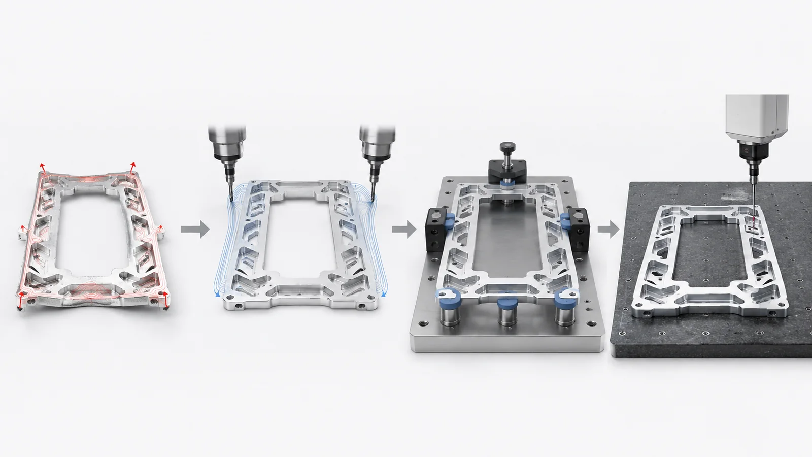
Distortion control requires a closed loop connecting residual stress, balanced material removal, low-stress fixturing and free-state inspection after unclamping.
1. Why an on-machine pass can become an unclamped failure
An on-machine result may only prove that the part matches the coordinate system while constrained.
If a fixture forces a bowed plate flat, or a side clamp lifts the part from its true support, machining creates a restrained geometry. Once released, the part seeks a new internal equilibrium and may show:
- plate bow;
- frame twist;
- inward or outward wall springback;
- misaligned bore axes;
- changed slot or opening width;
- inconsistent assembly gaps.
CTQs must state whether acceptance applies in the clamped, free or assembled condition.
2. Sources of residual stress
Two groups should be separated.
Residual stress already in the stock
Possible sources include:
- rolling and stretching;
- extrusion;
- forging;
- casting and cooling;
- solution treatment, quenching and aging;
- flattening and straightening;
- supplier and lot variation.
A visibly flat blank does not prove that stress is uniform through the thickness or along its length.
Stress generated by machining
Machining can add stress through three primary mechanisms:
- Cutting heat: local expansion followed by nonuniform cooling and contraction;
- Mechanical indentation and shear: local plastic deformation beneath the cutting edge;
- Tool wear or unsuitable conditions: cutting changes into rubbing, ploughing and work hardening.
For aluminum, adhesion, built-up edge, poor chip evacuation and localized heat make thin sections especially sensitive.
3. How cutting heat creates stress
Friction among tool, chip and workpiece produces heat. Thin regions have low thermal mass and rise in temperature quickly. If neighboring thick sections or the fixture remain cooler, a temperature gradient develops.
local heating and expansion
→ surrounding structure restricts expansion
→ cooling and contraction after the tool passes
→ surface and core contract differently
→ residual stress and shape change
Coolant control is therefore about stable heat removal, not simply maximum cooling. Intermittent delivery, changing nozzle position or local quenching can increase thermal cycling.
4. Why worn tools increase distortion
A sharp edge cuts. A worn edge is more likely to:
- rub;
- plough;
- adhere;
- form built-up edge;
- harden the surface;
- increase force and temperature.
A light final allowance does not guarantee a light mechanical load if the edge is dull. The wall may be pushed aside during cutting and spring back afterward.
Production records should include:
- tool life;
- edge condition;
- spindle-load trend;
- surface pattern;
- burr trend;
- first-to-last-part free-state dimensions.
5. Why one-sided heavy removal is high risk
Residual stress in the blank is temporarily balanced. Removing a large volume from one side removes only part of that load-carrying structure, so the remaining stress field redistributes and the part may bend toward or away from the machined side.
High-risk geometries include:
- a large cavity on one face;
- strongly unequal wall thickness;
- long plates;
- large frames;
- eyewear frames, panels and covers;
- liquid-cooling plate halves;
- lightweight robot housings;
- optical and electronic thin-wall enclosures.
The process should release material in stages and as symmetrically as practical.
6. Balanced removal and staged machining
A typical route is:
align the blank
→ alternate roughing between both faces
→ retain uniform stock
→ unclamp and observe
→ stabilize when required
→ re-establish datums
→ semi-finish
→ inspect again after release
→ final finish
The goal is not mathematically identical removal on every face. It is to avoid suddenly removing most of the stiffness from one side.
For frames, also plan:
- opening sequence;
- how long ribs remain;
- when process bridges are cut;
- internal versus external contour order;
- timing of large bores and threads;
- whether the final thin wall is produced last.
7. Why roughing and finishing should be separated
Roughing removes most stock and releases the dominant stress. It should not also be responsible for final dimensional acceptance.
Finishing should:
- establish final size after the part has rebalanced;
- use a stable tool and thermal condition;
- correct geometry with lower force;
- preserve the relationship among final datums and critical bores.
Continuous rough-and-finish machining can leave the part hot and restrained until it leaves the machine.
8. Intermediate stabilization is not blind heat treatment
General metalworking practice may use stress-relief annealing or an intermediate heat treatment between roughing and finishing. Aluminum alloys require more caution:
- allowable temperature depends on alloy and temper;
- unsuitable temperature or time can change strength, hardness and corrosion performance;
- a thermal cycle can create new shape change;
- customer specifications may prohibit additional heat treatment.
Intermediate stabilization can instead mean:
- a natural hold;
- a specified waiting period after roughing;
- controlled low-temperature stabilization;
- a supplier-approved stress-relief process;
- release, flip and re-alignment after roughing;
- a pilot-validated process window.
Any thermal method must be compatible with the specified material condition and performance.
9. Why side clamping helps top-surface machining
Side clamps apply force from the edge, leaving the top face clear and reducing interference with the spindle, holder and cutter. They are useful for:
- small parts;
- thin plates and frames;
- multi-part fixtures;
- workpieces requiring complete top-face access;
- irregular profiles that can use dedicated jaws.
A simple horizontal push can make a workpiece climb at the contact interface and lift away from the bottom datum.
For high-accuracy thin parts, a more effective clamp introduces both:
- a horizontal component toward the side locator;
- a controlled vertical component toward the bottom support.
This hold-down action reduces lift, but the downward force must not flatten the part artificially.
10. Five principles for low-stress side clamping
Place clamp force near support
Transmit force into a supported region rather than bending a wall between support points.
Use a downward component to prevent lift
Seat the part on the datum instead of relying only on lateral friction.
Protect aluminum with softer contact material
Aluminum, brass or other soft jaw materials can reduce marks. A soft jaw does not justify unlimited force.
Match irregular profiles
Machinable contour jaws distribute load and reduce point contact, slip and indentation.
Support flexible regions without lifting them
Auxiliary supports can suppress vibration and cutting deflection, but should contact a naturally seated part rather than jack it into a different shape.
11. More clamping force is not always more stable
Insufficient force allows slip. Excessive force can:
- flatten the part;
- mark the wall;
- locally yield a thin section;
- distort the bottom face;
- cause springback after release;
- create operator-dependent results.
Production should control:
- tightening torque;
- hydraulic or pneumatic pressure;
- clamping sequence;
- number of clamps;
- jaw condition;
- support height;
- cleanliness of the locating surfaces.
12. Multi-part fixtures: productivity and risk
Compact or double-sided clamps improve table utilization and reduce clamping operations. They can also introduce:
- unequal force among stations;
- chips under some datum faces;
- different stiffness at the middle and ends;
- changing tool temperature through the sequence;
- first-to-last-part drift;
- interaction between paired workpieces.
Each station should be identified and analyzed. One representative part is not enough.
13. Cutting conditions and coolant
For distortion-sensitive aluminum parts:
- use sharp tooling suited to aluminum;
- avoid rubbing with worn edges;
- maintain reliable chip evacuation;
- deliver coolant consistently to the cut;
- avoid repeated heat cycles from interruptions;
- rough efficiently without excessive ploughing;
- reduce radial load during finishing;
- avoid sudden full-width engagement at a thin edge;
- stabilize the machine and part thermally before final cuts.
Fixed numbers cannot be separated from wall thickness, tool overhang, fixture stiffness, spindle and material condition.
14. Datum transfer and re-clamping
A flip changes more than cutting direction. It changes:
- support locations;
- force path;
- gravity direction;
- thermal state;
- contact on already machined faces;
- remaining stock distribution.
After major re-clamping, confirm:
- real three-point support;
- no chips or burrs under the part;
- datum-face movement before and after release;
- no second flattening of a finished thin wall;
- no over-constraint from locating pins.
15. Free, restrained and assembled inspection states
| State | What it proves | Main risk |
|---|---|---|
| Fixture-restrained | Relationships while held on the machine | Can hide springback and bow |
| Free state | Stability of the part itself | Inconsistent support can change readings |
| Inspection fixture | Geometry under a defined locating scheme | Gauge force can constrain the part again |
| Assembled state | Real functional relationship | Screws may pull the part flat and add stress |
| Post-finish free state | Final delivered stability | Pretreatment and thermal cycles may reveal distortion |
Drawings should identify the required state for flatness, profile and position.
16. Why inspection is needed after anodizing
Anodizing pretreatment may include cleaning, etching, matting, rinsing and temperature exposure. A thin part already near its stability limit may reveal:
- unreleased roughing stress;
- wall-thickness imbalance;
- stock-lot differences;
- unbalanced local removal;
- pre-existing slight bow.
The validation chain should include:
free state after finishing
→ condition after pre-anodize cleaning
→ condition after anodizing and sealing
→ final assembly condition
17. Common failures and corrections
| Failure | Common cause | Corrective direction |
|---|---|---|
| Flatness fails after release | Fixture flattening and one-sided removal | Lower force, balance roughing and inspect free state |
| Wall springs inward | High finishing force | Sharp tool, lower radial load and temporary support |
| Part lifts during machining | Horizontal side force only | Use a side clamp with hold-down component |
| Aluminum is marked | Hard point contact and high torque | Soft jaw, larger contact and torque control |
| Irregular part slips | Jaw does not match profile | Machinable contour jaw or dedicated fixture |
| Stations differ | Unequal fixture stiffness and force | Station IDs, station-by-station data and standardized clamping |
| Part moves after machining | Heat and new residual stress | Stable coolant, rough-finish separation and intermediate observation |
| Part warps after anodizing | Pretreatment releases remaining stress | Pre- and post-anodize inspection and improved removal balance |
| Lot drift | Stock state or tool-life change | Material traceability, tool-life control and SPC |
18. Building the production window
confirm material and stock state
→ identify high-removal and flexible regions
→ design a balanced removal sequence
→ design low-stress support and hold-down clamping
→ rough prototype
→ unclamp and measure
→ stabilize when required
→ semi-finish and finish
→ remeasure free state
→ verify after surface treatment
→ validate assembly
→ freeze tool life, clamping force and inspection frequency
Recommended records:
- stock lot and supply condition;
- stock removed at each stage;
- fixture ID and clamping torque;
- tool ID and life;
- coolant condition;
- distortion after roughing;
- change before and after stabilization;
- final free-state result;
- change after anodizing;
- assembly function.
19. RFQ information
| RFQ input | Engineering use |
|---|---|
| Alloy and temper | Assess stability and thermal-treatment limits |
| Stock form and supply state | Identify original stress sources |
| Controlled 2D drawing and 3D model | Identify thin walls, cavities, frames and asymmetric removal |
| Free-state tolerance | Define final acceptance |
| Assembly constraint | Separate part stability from assembly pull-down |
| Permitted clamping and cosmetic faces | Plan side clamps, soft jaws and supports |
| Datum scheme | Plan flips and re-location |
| Surface treatment | Assess downstream dimensional change |
| Inspection state and support method | Align measurement results |
| Annual demand and batch size | Evaluate multi-part fixtures and dedicated jaws |
| Prototype and production timing | Plan roughing observation and stabilization trials |
Before quotation, confirm:
- the state in which flatness and profile are accepted;
- whether process bridges or temporary ribs are permitted;
- whether a hold or stabilization step is allowed after roughing;
- which faces may be clamped or show minor contact;
- whether post-treatment inspection is required;
- whether volume justifies a dedicated low-stress fixture.
Frequently asked questions
Why can an aluminum part pass inspection on the machine and distort after unclamping?
The fixture may force a naturally distorted part against the datum, so the machine sees a restrained condition. After unclamping, stock residual stress, machining stress and elastic fixture deformation rebalance, causing springback, bow or twist. A free-state inspection after unclamping is therefore required.
Do thin-wall aluminum parts need aging or stabilization after rough machining?
For high material removal, long tolerance chains, tight flatness or finishing-sensitive thin parts, a validated natural hold, controlled thermal stabilization or other stress-release step after roughing can be useful. Temperature and time must match the alloy and temper and must not damage the specified material properties.
How can side clamping prevent lift and marking on a thin aluminum part?
Apply force near support points and use a hold-down geometry that adds a controlled downward component so the part remains seated. Aluminum, brass or other soft contact materials can reduce marking, while irregular workpieces benefit from contour-matched machinable jaws and auxiliary supports rather than high horizontal force alone.
What information is required for an aluminum distortion-control RFQ?
Provide alloy and temper, stock form, controlled 2D drawings and 3D model, final free-state tolerances, permitted clamping and cosmetic surfaces, machining stock, surface finish, assembly constraints, inspection state, volume, prototype timing and whether intermediate stabilization or post-finishing is allowed.
