
In This Article
Direct answer
Grinding and polishing are not final rescue operations for a cosmetic part, and the objective is not always maximum brightness.
Four questions must be answered first:
- Which defects must be removed?
- Which dimensions, edges and textures must not be changed?
- Is the final target matte, brushed, semi-gloss, high-gloss or mirror, or is the surface a base for anodizing, painting, plating or PVD?
- Can the prototype result be repeated in production?
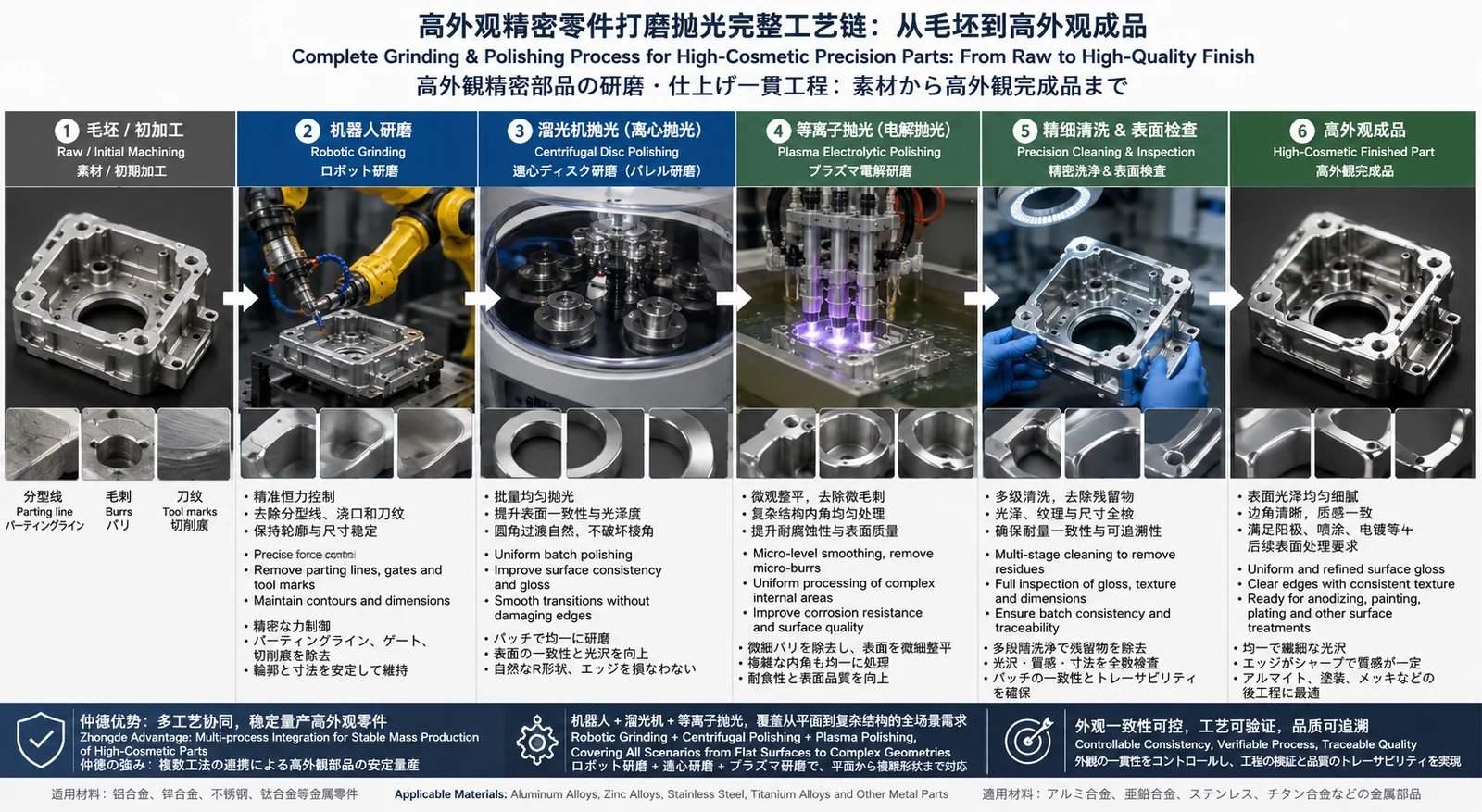
A typical route is:
casting and class-A surface analysis
→ gate and burr removal
→ staged robotic or manual grinding
→ buffing, barrel finishing or electrolytic-plasma finishing
→ cleaning and base-surface unification
→ anodizing, painting, plating or PVD
→ cosmetic, dimensional and assembly reinspection
The difficult capability is not owning one polishing machine. It is combining multiple methods with the final coating according to material, geometry, defect type, cosmetic grade and production quantity.
1. What is high-cosmetic grinding and polishing?
High-cosmetic grinding and polishing means removing controlled amounts of material without damaging function or geometry and creating a texture and reflection that can be accepted and reproduced.
Typical requirements include:
- parting lines, gate marks and flash are no longer obvious;
- burrs, sharp edges and opening conditions are controlled;
- CNC marks, tool transitions and local hand-finishing marks remain within limits;
- class-A surfaces have no obvious waves, depressions, bright spots or dark spots;
- planes, curves, radii and styling lines retain the intended geometry;
- adjacent regions have coordinated texture direction, fineness and gloss;
- no polishing compound, abrasive or oil remains after cleaning;
- the appearance remains acceptable after anodizing, painting or plating;
- prototype, pilot and production parts use the same acceptance criteria.
High-cosmetic polishing is therefore a manufacturing process that controls dimension, shape, surface and production repeatability together.
2. Grinding, sanding, polishing and finishing
The terms are often used interchangeably in factories, but the engineering objectives differ.
| Operation | Main purpose | Typical removal | Typical result |
|---|---|---|---|
| Coarse grinding | Remove gates, parting lines, flash and high spots | Relatively high | Establish basic contour |
| Intermediate sanding | Remove coarse marks, tool marks and local waviness | Medium | Unify texture and transitions |
| Fine sanding | Progressively reduce scratches and roughness | Low | Prepare for polishing or coating |
| Buffing | Increase brightness and reduce fine scratches | Very low | Semi-gloss, high-gloss or mirror preparation |
| Barrel finishing | Batch deburring, edge softening and general smoothing | Low and distributed | Uniform edges and small-part surfaces |
| Plasma electrolytic polishing | Micro-leveling and micro-deburring on compatible materials | Very low | Smooth complex surfaces |
| Blasting | Create controlled diffuse or functional texture | Controlled | Matte base or functional surface |
One part often uses a sequence rather than one operation.
3. High cosmetic does not always mean maximum gloss
Different products define premium appearance differently.
| Appearance target | Main control |
|---|---|
| Uniform matte | Media, diffuse reflection, bright spots and regional uniformity |
| Fine brushing | Direction, line spacing, depth and transition |
| Semi-gloss metal | Balance between retained texture and brightness |
| High gloss | Fine scratches, waviness, pits and edges |
| Mirror | Flatness, very low roughness, clear reflection and cleanliness |
| Base for anodizing | Material and texture uniformity without local over-polishing |
| Base for painting | Adhesion roughness and removal of visible defects |
| Base for plating or PVD | Very low defects, flatness and contamination control |
Over-polishing an area that should remain matte can create a bright patch and make the part less acceptable.
4. Why premium parts need a process combination
One robot, buffing wheel or barrel cannot solve every surface problem.
A cosmetic part may include:
- planes;
- continuous curves;
- small radii;
- internal corners;
- deep grooves;
- openings;
- bosses;
- assembly datums;
- thin walls;
- styling edges that must stay sharp.
Each region needs a different contact method, abrasive, force and protection strategy. The value of a complete capability is:
prevent forming defects
→ design CNC allowance and texture
→ automate repeatable primary removal
→ detail inaccessible regions manually
→ process suitable small parts in batch
→ perform fine polishing and cleaning
→ apply the final surface treatment
→ close the loop with cosmetic and dimensional inspection
5. Challenge one: removing die-cast parting lines, gates and flash
Typical die-cast preparation includes:
- gate remnants;
- parting lines;
- overflow areas;
- ejector surroundings;
- flash;
- die scratches;
- local raised areas.
The challenge is not only removing them. The surface must not develop:
- local depressions;
- wavy edges;
- left-right asymmetry;
- inconsistent radii;
- class-A scratches;
- damaged assembly datums.
Large stock removal should be separated from fine cosmetic correction, with clear datums and removal boundaries for robots or dedicated fixtures.
6. Challenge two: CNC tool marks and tool transitions
A machined surface can include:
- milling scallops;
- turning spirals;
- tool transition lines;
- different toolpath directions;
- gloss changes caused by tool wear;
- residual high spots at plane-to-curve transitions.
These marks may become more visible after anodizing, plating or bright finishing.
Increasing polishing time alone is not the answer. Review:
- CNC tool condition;
- toolpath direction;
- finishing allowance;
- feed and speed;
- texture direction across operations;
- whether the whole visible base should be blasted, brushed or fine-ground.
7. Challenge three: flow marks, pits and porosity
Controlled grinding can reduce light flow marks or shallow surface high spots, but it cannot remove internal:
- gas porosity;
- shrinkage;
- porous regions;
- oxide inclusions;
- deep pitting.
Continuing to remove material can expose more pores, create depressions, reduce wall thickness, distort the contour and reveal defects again after coating.
The first decision is whether a defect is a removable surface condition or a substrate problem that must be corrected during forming.
8. Challenge four: automation on curves and internal features
Robots and buffing wheels work well on broad surfaces, continuous curves and external contours, while the following can become blind zones:
- deep cavities;
- narrow grooves;
- small internal corners;
- inside edges of openings;
- boss roots;
- curve transitions;
- abrupt contour changes.
Poor tool access creates under-processing, over-processing or collision risks.
Solutions include:
- improving tool access during design;
- using different tool diameters and profiles;
- assigning major visible faces to robots;
- limiting inaccessible regions to standardized manual stations;
- evaluating barrel or plasma-electrolytic methods where appropriate.
9. Challenge five: thin-wall distortion
Thin housings, frames and broad panels are sensitive to contact force and heat.
Risks include:
- panel warp;
- frame opening or closing;
- hole-position change;
- local collapse;
- abnormal assembly gaps;
- fixture marks;
- heat discoloration.
Control:
- support area;
- clamping points;
- grinding pressure;
- continuous contact time;
- part temperature;
- path sequence;
- flipping method;
- free-state reinspection.
A cosmetic surface and compliant dimensions must be achieved together.
10. Challenge six: excessive polishing damages geometry
Although polishing removal is generally low, it can become concentrated at edges, openings and high spots.
Over-processing can cause:
- loss of sharp styling lines;
- larger radii;
- enlarged openings;
- reduced flatness;
- blurred text or logo boundaries;
- reduced local wall thickness;
- softened step boundaries;
- different geometry between left and right parts.
Class-A surfaces need stock-removal limits, while critical boundaries require protective fixtures, masking or mechanical stops.
11. Challenge seven: manual variation
Manual results are affected by:
- operator experience;
- tool angle;
- contact pressure;
- dwell time;
- abrasive condition;
- compound quantity;
- inspection lighting;
- number of rework cycles;
- fatigue.
Manual finishing can produce excellent quality, but experience must be translated into:
standard tool
→ fixed abrasive grade
→ defined sequence
→ time limit
→ dedicated fixture
→ physical limit samples
→ in-process inspection
12. Challenge eight: matching the final surface treatment
The polished part may still require:
- anodizing;
- painting;
- e-coating;
- plating;
- PVD;
- laser marking;
- printing;
- assembly.
Each system retains, covers or amplifies the base differently.
Maximum brightness cannot be the universal standard. Abrasive grade, texture, roughness and cleaning must be defined backward from the final surface.
13. What robotic grinding is good at
Robotic grinding is suitable for:
- regular external contours;
- broad cosmetic surfaces;
- continuous curves;
- parting lines;
- gate regions;
- repeated higher-volume products;
- operations requiring repeatable paths and cycle times.
Its value comes from repeatable control of:
path
→ contact angle
→ feed speed
→ contact force
→ tool speed
→ number of passes
→ abrasive-life compensation
A fixed path alone is insufficient. Part variation, tool wear and contact force can still cause missed areas, over-grinding, heat and waviness.
14. Why robotic grinding still needs fixturing and force control
Surface finishing is a contact process. Casting variation, locating error and tool wear all change actual pressure.
A stable system normally needs:
- repeatable fixturing;
- suitable compliance;
- contact-force control;
- tool-wear monitoring;
- path compensation;
- staged abrasives;
- first-piece and patrol samples.
Robots improve repeatability but do not remove inconsistency in the incoming part.
15. What buffing is suitable for
Buffing is commonly used for:
- semi-gloss;
- high-gloss;
- external contours;
- large radii;
- decorative curves;
- brightness after fine sanding;
- local bright edges.
Key variables:
- wheel material and hardness;
- wheel construction;
- rotational speed;
- polishing compound;
- contact pressure;
- dwell time;
- workpiece direction;
- wheel dressing and replacement;
- heat and cleanliness.
Buffing removes fine scratches but should not replace leveling. A wavy or pitted base becomes shiny but remains uneven.
16. What barrel finishing is suitable for
Barrel or related mass-finishing methods are suitable for:
- small parts;
- multi-edge geometries;
- batch deburring;
- light edge rounding;
- edge uniformity;
- general surface smoothing;
- parts that are too costly to finish individually.
Key variables:
- media material;
- media shape and size;
- part-to-media ratio;
- compound;
- rotational or motion condition;
- time;
- load;
- part-on-part contact;
- cleaning and corrosion prevention.
Do not assume it is suitable for every class-A face. Thin parts, damage-sensitive surfaces, precision threads and sharp styling edges may need protection or a different route.
17. What plasma electrolytic polishing can do
Plasma electrolytic polishing uses a compatible electrolyte and energetic surface action to preferentially smooth microscopic peaks.
It may be suitable for:
- micro-burrs;
- complex contours;
- zones difficult to reach mechanically;
- whole-surface micro-leveling;
- reduction of directional mechanical marks;
- brightening and cleaning of compatible materials.
Important limits:
- the material and alloy must be compatible;
- a very rough initial surface still needs prior grinding and leveling;
- deep pits, pores and geometric errors do not disappear;
- electrolyte, temperature, voltage, time and racking affect the result;
- material removal at critical dimensions and edges must be validated;
- aluminum, die-cast aluminum and other metals cannot use one universal parameter set.
It is a precision finishing tool, not a universal shortcut to a mirror finish.
18. Why manual detailing remains necessary
High-volume cosmetic production does not always eliminate manual work.
Manual detailing remains useful for:
- deep grooves;
- internal corners;
- openings;
- complex transitions;
- occasional small defects;
- prototypes and low volumes;
- regions a robot cannot approach safely.
The manual scope must be restricted. Define:
- permitted zones;
- tool and abrasive;
- maximum time;
- maximum removal;
- final texture direction;
- inspection and release criteria.
19. How to combine processes
| Part challenge | Primary process | Supporting process |
|---|---|---|
| Parting line and gate | Robotic rough grinding or dedicated removal | Manual detailing |
| Broad regular cosmetic face | Staged robotic grinding | Buffing |
| High-gloss decorative face | Staged fine sanding | Buffing |
| Batch burrs on small parts | Barrel finishing | Local inspection and protection |
| Internal corner or deep groove | Standardized manual detailing | Small special tools |
| Micro-burr and complex contour | Plasma-electrolytic trial | Pretreatment and dimensional validation |
| Uniform base before anodizing | Fine sanding, blasting or brushing | Cleaning and lot control |
| Base before painting | Deburring and leveling | Blasting or chemical pretreatment |
| Bright base before plating or PVD | Multi-stage fine sanding and buffing | Precision cleaning |
20. Selecting abrasive grades
Jumping directly from a coarse abrasive to fine polishing often leaves deep scratches underneath.
The correct concept is:
remove major high points
→ eliminate scratches from the previous grade
→ unify direction and texture
→ refine roughness
→ polish or create the final base
Each operation should confirm that the deepest marks from the previous step have been removed before moving to the next grade.
Too many stages also increase cost, edge removal and manual variation, so the sequence must remain efficient.
21. How fixtures protect dimensions and appearance
A finishing fixture does more than hold the part. It can:
- support thin walls;
- limit distortion;
- protect assembly surfaces;
- mask regions that must not be polished;
- provide a robot datum;
- control contact direction;
- prevent part release;
- keep fixture marks outside class-A areas.
For left-right pairs or multi-cavity parts, the fixture also aligns orientation to prevent mirrored texture and position differences.
22. Why cleaning is part of polishing
Typical residues include:
- polishing compound;
- abrasive powder;
- metal dust;
- oil;
- barrel compound;
- fixture contamination;
- fingerprints.
They affect:
- anodizing pretreatment;
- coating adhesion;
- plating defects;
- PVD bonding;
- laser marking;
- cosmetic inspection;
- assembly cleanliness.
Cleaning capability must be evaluated with polishing capability, not strengthened only after a coating failure.
23. How high-cosmetic parts should be inspected
Recommended checks include:
- visual inspection under defined lighting;
- fixed distance and viewing angle;
- target and upper/lower limit samples;
- surface roughness;
- gloss;
- texture direction;
- waviness and local height difference;
- critical radii;
- openings and styling edges;
- flatness and contour;
- post-finish critical dimensions;
- assembly gaps;
- cleanliness.
Visual and dimensional inspection must be linked. A beautiful part that fails assembly is not acceptable.
24. Prototype-to-production validation route
Recommended route:
define class-A surfaces and final coating
→ evaluate incoming defects and machining allowance
→ trial process combinations
→ screen abrasive, force, path and time
→ validate the final surface treatment
→ reinspect appearance and dimensions
→ establish physical limit samples
→ validate pilot cycle time and tool life
→ freeze production parameters
Do not judge only the newly polished part. Inspect the final anodized, painted, plated or PVD result.
25. Common failures and corrective direction
| Failure | Main cause | Corrective direction |
|---|---|---|
| Local depression | Excess dwell or force | Reduce force and dwell, optimize path |
| Wavy reflection | Uneven base and excessive buffing | Improve prior leveling and reduce heavy buffing |
| Rounded styling edge | Concentrated removal and no protection | Set stock limit and add masking or fixture |
| Mixed texture direction | Inconsistent manual path | Fix direction and operation sequence |
| Lot-to-lot gloss variation | Tool wear, compound and time drift | Manage tool life, compensation and cycle |
| Pits visible through paint | Substrate defects too deep | Level earlier or improve incoming part |
| Tool marks after anodizing | CNC and sanding bases differ | Optimize toolpath and unify the base |
| Contact damage after barrel finishing | Excess load and part collision | Adjust ratio, separation and time |
| Coating failure after polishing | Compound and oil residue | Improve matched cleaning and water-break check |
| Good prototype, unstable production | Operator dependence and unmanaged tool life | Standardize equipment parameters and limit samples |
26. Why a complete process chain matters more than one machine
The customer purchases an accepted cosmetic part, not minutes on a robot, buffing machine or barrel.
A complete process chain solves each problem at the most suitable point:
tooling and forming prevent root defects
→ CNC controls allowance and base texture
→ robots repeat the primary surface removal
→ buffing creates the target brightness
→ barrel finishing handles suitable small parts and edges
→ manual work is restricted to inaccessible regions
→ plasma electrolytic polishing is evaluated for complex micro-finishing
→ cleaning ensures coating compatibility
→ anodizing, painting or another treatment creates the final appearance
→ inspection and assembly confirm function
Managing these operations continuously is more reliable than assembling multiple unrelated suppliers after the design and defects have already been fixed.
27. RFQ information
| RFQ input | Engineering use |
|---|---|
| Controlled 2D drawing and 3D model | Evaluate access, edges and fixturing |
| Material and incoming process | Evaluate defects and polishing compatibility |
| Class-A, class-B and non-cosmetic surfaces | Allocate processes and inspection |
| Final surface treatment | Define the base route backward |
| Target gloss and texture | Select grinding, brushing, polishing or blasting |
| Parting-line, gate and burr locations | Plan removal paths |
| Edges that must remain sharp | Design protection and limits |
| Critical dimensions and GD&T | Control removal and distortion |
| Visual limit samples | Align production acceptance |
| Cleanliness requirement | Design cleaning and packaging |
| Prototype, batch and annual quantity | Select manual, robotic or mass finishing |
| Left-right and multi-cavity information | Control orientation and cavity variation |
Before quotation, confirm:
- whether “polished” means matte, semi-gloss, high-gloss or mirror;
- whether the final part will be anodized, painted, plated or PVD coated;
- which textures must be removed and which may remain;
- which dimensions and edges must not change;
- the permitted incoming substrate defects;
- whether dedicated robotic fixtures are required;
- whether slight edge rounding from barrel finishing is permitted;
- whether plasma electrolytic polishing is compatible with the material and geometry;
- whether appearance is judged by photos, color cards or physical limit samples;
- whether post-finish assembly validation is required.
Frequently asked questions
Can robotic grinding completely replace manual grinding and polishing?
No. Robots are effective on repeatable external surfaces with defined paths, stable fixturing and sufficient volume, and they improve consistency of contact force, speed and cycle time. Deep grooves, internal corners, openings, complex transitions and occasional defects may still require manual detailing. A more stable route uses the robot for primary stock removal and texture control while restricting manual work to clearly defined inaccessible zones.
What is the difference between a high-gloss finish and a mirror finish?
A high-gloss finish emphasizes brightness and uniform reflection but may still permit limited fine texture. A mirror finish requires lower roughness, clearer image reflection and stricter control of waviness, sanding marks, pits and substrate defects. Mirror quality needs much better prior leveling, material uniformity and cleanliness and cannot be achieved simply by increasing buffing time.
Can continued grinding remove porosity and pitting from a die casting?
Controlled grinding can improve shallow raised defects and light marks, but it cannot eliminate deep porosity, porous material or inclusions. Further stock removal may expose more pores, create local depressions and damage the contour. The defect depth and class-A allowance must be evaluated first, and the casting flow, venting, intensification, melt and die-temperature controls should be improved when the defect originates in the casting.
Do anodizing, painting and plating require the same polished base surface?
No. Anodizing retains and may emphasize substrate texture, so base-finish uniformity and material consistency are critical. Painting can cover some fine texture but cannot level clear pits or waves. Bright plating and PVD are more sensitive to flatness, sanding marks and contamination. The base-finish route must be designed for the final coating system, target gloss and defect limits.
