
In This Article
Direct Answer
A humanoid robot body shell is not merely a cosmetic skin. Chest panels, back covers, shoulder guards, arm shells and leg covers also provide impact protection, motion clearance, service access, local stiffness, cable protection, visual continuity and, in some cases, electromagnetic shielding.
The three manufacturing routes have different boundaries:
- Warm-formed magnesium sheet suits relatively uniform thin walls, continuous curves, metallic appearance and higher local stiffness.
- Injection-molded engineering plastics suit parts that integrate ribs, snaps, bosses, cable channels and complex surfaces.
- Carbon-fiber composites suit projects prioritizing specific stiffness, distal mass reduction and premium appearance.
The correct decision path is not “which material is lightest,” but:
Shell location and function
→ Segmentation and assembly strategy
→ Target volume and design maturity
→ Material and forming route
→ Trimming, drilling and local finishing
→ Surface, inserts and assembly
→ Free-state and robot-level validation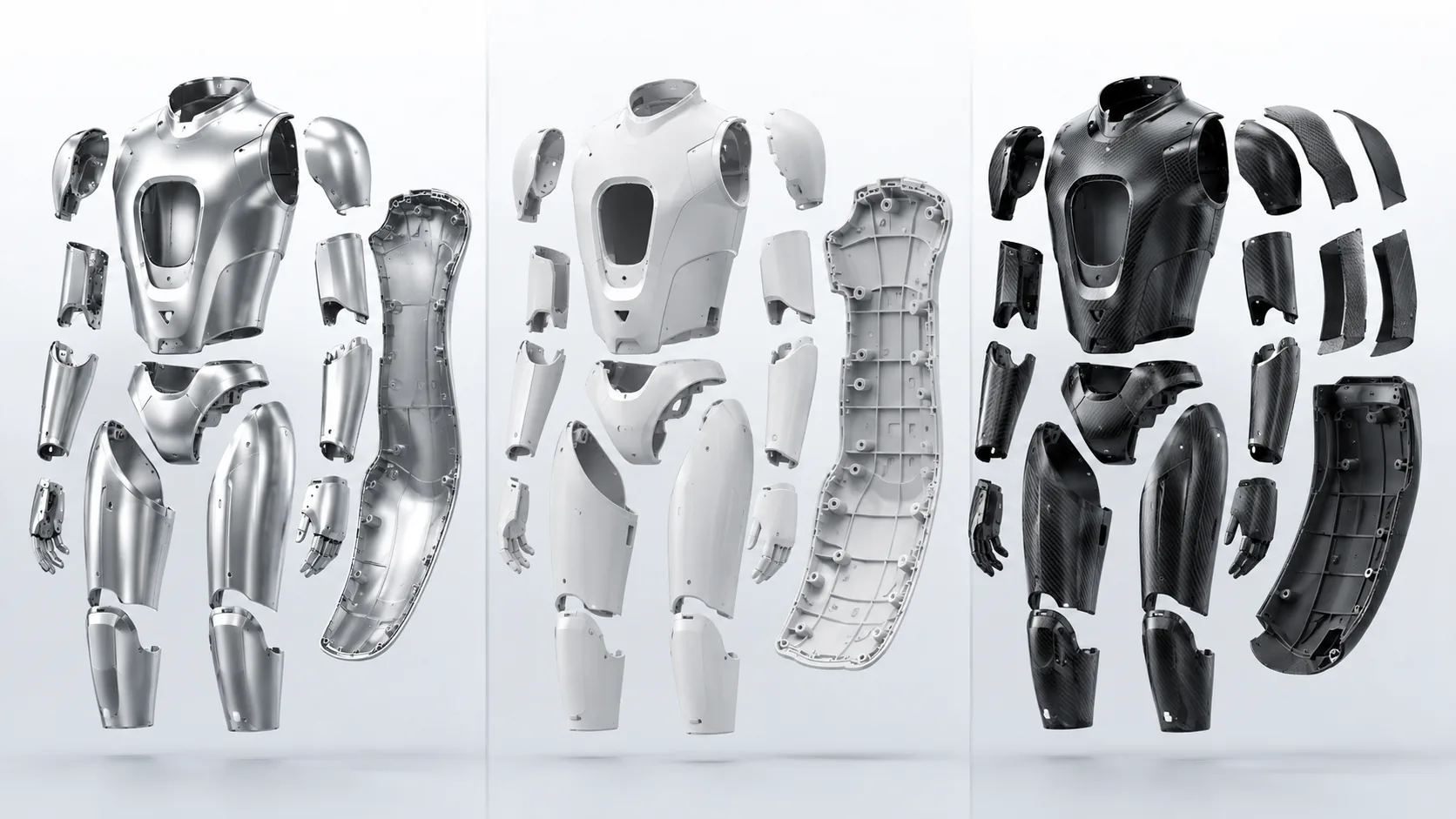
The same humanoid robot body panels can follow metallic sheet, injection-molded plastic, or carbon-fiber composite routes, with different implications for integration, tooling, secondary processing, and production.
1. Define what the shell must do
Requirements vary across the robot.
| Shell location | Main function | Most sensitive issues |
|---|---|---|
| Chest and back | Large-area protection, appearance and service access | Surface continuity, panel gaps, thermal management and shielding |
| Shoulder guard | Joint protection and motion clearance | Interference, impact and replacement |
| Upper arm and forearm | Lightweighting, cable protection and styling | Rotational inertia, hole position and left-right consistency |
| Thigh and lower leg | Large curved surfaces, impact protection and appearance | Weight, dent resistance and edge gaps |
| Articulated joint cover | Pinch protection, dust control and maintenance | Toughness, rubbing and removal cycles |
| Internal electronics cover | Insulation, shielding and component retention | Flame behavior, temperature, bosses and cable management |
A practical robot therefore uses zoned material selection. The chest panel, joint guard, forearm shell and electronics enclosure do not need to use the same material.
2. Marketing terms are not complete material specifications
Terms such as “aerospace grade,” “ultralight” and “magnesium-aluminum alloy” are often used in product communication, but they cannot replace a technical material definition.
“Magnesium-aluminum alloy” may refer to two different systems:
- a magnesium-base alloy containing aluminum and other alloying elements;
- an aluminum-base alloy in which magnesium is a major alloying element.
Their density, forming behavior, corrosion protection, joining, machining and finishing routes differ. An RFQ should identify at least:
- material grade and applicable specification;
- sheet, molding compound or composite system;
- temper, sheet thickness or reinforcement content;
- fiber type, resin and layup requirements where applicable;
- finish and color;
- rules for equivalent-material substitution.
In this article, magnesium warm forming means forming a magnesium-base alloy sheet under controlled heating, not treating magnesium sheet and aluminum-magnesium sheet as the same material.
3. Warm-formed magnesium sheet: the metallic thin-shell route
3.1 Typical manufacturing chain
Magnesium sheet receiving
→ Blank cutting and direction marking
→ Sheet and tool heating
→ Preforming or warm forming
→ Restraining and springback compensation
→ Trimming and piercing
→ Local CNC machining or precision cutting
→ Deburring and cleaning
→ Corrosion pretreatment and coating
→ Inserts, fasteners and assembly
→ Profile, gap and appearance inspection
Magnesium-sheet formability depends on temperature, strain rate, rolling direction, thickness and draw depth. Warm forming is not simply “heating the material until it becomes soft.” It is a controlled method for widening the forming window and reducing cracking and springback risk.
3.2 Structures that fit this route
Warm-formed magnesium is better suited to:
- broad continuous surfaces;
- relatively uniform wall thickness;
- shells without dense deep ribs or complex molded bosses;
- parts requiring metallic feel and local dent resistance;
- designs where interfaces can be provided by separate brackets, inserts or secondary machining;
- quantities sufficient to amortize forming tools and checking fixtures.
If the rear surface requires many integral snaps, screw bosses, cable channels and dense rib networks, injection-molded engineering plastic is usually easier to integrate.
3.3 Why the tooling can be simpler than a large die-casting tool
For a shallow continuous shell without complex undercuts, a warm-forming tool mainly contains punch, die, blank holding, location and thermal-control features. It does not require the high-pressure metal-flow system, overflow and venting, extensive ejection and thermal balancing associated with die casting. Warm forming is therefore often worth evaluating for a large thin shell.
However, “simpler tooling” does not mean “no tooling development.” A complex shell may still need:
- a preforming tool;
- a main forming tool;
- springback compensation and restrike tooling;
- trimming and piercing tooling;
- a contoured CNC fixture;
- a completed-shell checking fixture.
Deeper surfaces, tighter cosmetics and stricter left-right matching increase the complete tooling package.
3.4 Main manufacturing risks
| Risk | Possible result | Control direction |
|---|---|---|
| Unstable temperature | Cracking, incomplete forming or lot variation | Control heating, transfer and forming windows |
| Changed material direction | Different behavior between mirrored parts or nesting positions | Preserve rolling-direction and nesting records |
| Excessive local strain | Thinning, cracks or rough surface | Optimize radii, blank holding and forming stages |
| Springback | Shifted surface, edge or mounting position | Tool compensation, restrike and free-state measurement |
| Tool marks or trapped particles | Cosmetic dents and scratches | Protect show surfaces and control tool cleanliness |
| Forced secondary clamping | In-fixture acceptance but free-state distortion | Use contoured support and low clamping force |
4. Injection-molded engineering plastics: the integration route
4.1 Typical manufacturing chain
Material and color definition
→ Flow and structural DFM
→ Injection mold
→ Tool trials and shrinkage compensation
→ Injection molding
→ Gate removal and cosmetic finishing
→ Insert or nut installation
→ Optional coating, texture or conductive treatment
→ Assembly and dimensional validation
The main advantage of engineering-plastic shells is not simply low density. It is the ability to integrate many functions into one molded part:
- stiffening ribs;
- snaps;
- mounting bosses;
- threaded inserts;
- cable channels;
- vents and local shields;
- texture and color.
This can reduce separate brackets, fasteners and CNC operations, but it also concentrates more functions into the mold and molding window.
4.2 Why it suits larger volumes
Once the mold and process are stable, injection molding provides short cycles and high repeatability. The more parts produced and the more functions integrated, the easier it is to amortize the mold and reduce assembly content.
The risk is committing to production tooling before the design is mature. Boss positions, split lines, gates, ejector marks, texture, snaps and assembly sequence should be reviewed before tool release.
4.3 Risks are more complex than “plastic is weak”
| Risk | Effect on the shell |
|---|---|
| Differential shrinkage | Warpage and shifted holes or edges |
| Abrupt wall-thickness changes | Sink marks, residual stress and uneven cooling |
| Fiber orientation | Directional shrinkage, stiffness and surface appearance |
| Long-term creep | Slow change in preload, snaps and boss position |
| Weld lines | Cosmetic or local structural weak regions |
| Stress around inserts | Cracking, distortion or reduced removal life |
| Heat and chemical exposure | Changes in stiffness, dimensions and surface aging |
Engineering-plastic shells therefore require material, ribs, gates, cooling, fiber orientation, inserts and assembly loads to be designed together.
5. Carbon-fiber composites: the layup-design route
5.1 Carbon fiber is not one fixed-property material
CFRP performance depends on:
Fiber type
× Fiber direction
× Layup sequence
× Resin system
× Resin content
× Cure or forming route
× Local reinforcement and inserts
Two shells with the same shape and nominal thickness can have different bending stiffness, impact response, hole-edge strength and distortion if the layup changes. A drawing that only says “carbon fiber” is therefore incomplete.
5.2 Manufacturing-route options
| Route | Main characteristic | Better fit |
|---|---|---|
| Prepreg layup and cure | Controlled surface and layup, more labor and cycle time | Premium, low-to-medium volume |
| Compression molding | Better cycle and repeatability, dedicated tooling required | Medium and higher volume |
| Resin infusion or RTM | Suitable for large curves, process window must be controlled | Low-to-medium volume |
| Thermoplastic composite forming | Potential for faster forming and secondary joining | Production routes requiring system validation |
CFRP should not be reduced to “hand-laid fabric.” The route should match volume, appearance, structural performance, cycle time and investment.
5.3 Secondary machining and joining drive cost
A formed CFRP shell commonly still requires:
- trimming;
- drilling;
- sensor and cable windows;
- metal inserts;
- bonded brackets;
- filling, coating or clear finishing;
- checks for delamination, hole-edge damage, voids and cosmetics.
During drilling and trimming, fiber direction, tool condition, support and cutting load affect delamination, fiber pull-out and hole quality. Fine fiber dust is also generated, requiring dedicated extraction, housekeeping and personal-protection controls.
5.4 Metal inserts require load-path design
Screws, locating pins and repeated-service interfaces often need metal inserts. The design should consider:
- load-spreading area;
- local layup reinforcement;
- bond-line thickness and cure;
- insert anti-rotation and pull-out resistance;
- electrical isolation between carbon fiber and metals;
- differential thermal expansion;
- repair and replacement strategy.
6. Engineering comparison of the three routes
| Comparison item | Warm-formed magnesium | Injection-molded engineering plastic | CFRP composite |
|---|---|---|---|
| Large continuous curves | Priority candidate | Suitable | Suitable |
| Integrated ribs, snaps and bosses | Limited; separate features often required | Strong advantage | Usually uses inserts and bonding |
| Metallic feel and conductivity | Strong advantage | Requires added surface or conductive system | Must be validated by layup and surface system |
| Specific stiffness and distal mass reduction | Good | Depends on material and geometry | Strong potential but direction-sensitive |
| Initial tooling | Often manageable for simple curves | Production mold can be costly | Varies widely by layup, molding and cure route |
| Design-change flexibility | Better in soft-tool stage, lower after production tooling | Expensive after production tool release | Low-volume layup routes can be more flexible |
| High-volume cycle | Medium | Strong advantage | Depends on molding and cure cycle |
| Precision local interfaces | Trim, pierce or CNC-machine | Molded or lightly finished | Trim, drill and add inserts |
| Cosmetic risks | Dents, scratches and coating variation | Weld lines, sink, color and texture | Weave variation, resin-rich areas, pinholes and seams |
| Long-term risks | Corrosion protection, dents and joint interfaces | Creep, aging, snaps and boss cracking | Delamination, impact damage, bonding and repair |
| Secondary-process safety | Magnesium chips and dust need dedicated control | Usually lower; reinforced grades still need control | Fiber dust needs dedicated control |
| Recycling and repair | Metal recycling route is relatively clear | Depends on resin and reinforcement | Thermoset systems are harder to repair and recycle |
This table supports early screening only. Final selection must return to specific geometry, thickness, assembly and production volume.
7. Tooling cost is more than one mold quotation
Initial project investment normally includes:
Forming or injection mold
+ Trimming and drilling fixtures
+ Insert tooling
+ Cosmetic boundary samples
+ Single-part checking fixture
+ Shell-assembly checking fixture
+ Trials and design changes
Warm-formed magnesium
A simple continuous surface can use relatively direct forming tools, but a complex part may need preforming, main forming, restrike and trimming tools.
Injection-molded engineering plastic
The mold must manage filling, packing, cooling, ejection, split lines and possible slides. Tool cost can be high, but integration and volume can lower unit manufacturing and assembly cost.
CFRP
Low-volume layup tooling can be flexible, while labor, cure and finishing remain expensive. Compression molding or automated routes increase tooling and equipment investment.
A useful comparison includes:
Initial tooling
+ Unit material and processing
+ Scrap and rework
+ Assembly
+ Tool maintenance
+ Design changes
+ Service replacement
8. Structural integration and assembly interfaces
Warm-formed magnesium shell
Thin sheet should not carry every thread or high-preload joint directly. Common approaches include:
- separate metal brackets;
- riveted or controlled attachment hardware;
- local folds or doubled edges;
- adhesive and mechanical joining combinations;
- locating holes machined after shape stabilization.
Engineering-plastic shell
Bosses, snaps and ribs can be molded in, but the design must control:
- root radii;
- boss-to-wall proportions;
- screw installation cycles;
- stress around metal inserts;
- snap assembly and service life;
- preload retention at temperature.
CFRP shell
Loads should spread through inserts and local reinforcement. Holes and inserts should not be placed in an unreinforced thin laminate or concentrate assembly force only at a hole edge.
9. CTQs shared by all three materials
| CTQ | Functional impact |
|---|---|
| Key surface profile | Controls visual continuity |
| Panel-edge profile | Controls gap and flushness |
| Mounting and locating holes | Controls relationship to the internal frame |
| Left-right symmetry | Affects appearance, movement and replacement consistency |
| Joint-clearance zone | Prevents contact and rubbing during motion |
| Wall thickness or local thinning | Affects stiffness, impact and cosmetics |
| Boss, insert and joint region | Controls removal and fastening life |
| Cosmetic defect boundary | Defines acceptance and rework |
| Free-state profile | Prevents forced-fixture false acceptance |
| Assembled gap and flushness | Defines final robot appearance |
Free state and assembled state are different
Thin metal, molded plastic and composites can all be forced into position by fixtures or screws. Measuring only under constraint can hide part warpage.
A robust acceptance plan distinguishes:
- free-state single-part profile;
- datum fixture or simulated-frame condition;
- final robot gaps, flushness and motion clearance.
10. Surface, EMI and manufacturing safety
Warm-formed magnesium shell
Corrosion pretreatment, coating, scratch repair, grounding points and dissimilar-metal interfaces should be designed together. Warm forming itself usually does not create continuous large amounts of dust, but trimming, drilling, CNC machining, grinding and repair can generate magnesium chips or fine dust. These operations require dedicated combustible-metal chip and dust management.
Engineering-plastic shell
A plastic shell normally does not provide the same continuous conductive shielding as a metal shell. Conductive coatings, mesh, local metal parts or conductive compounds may be used, but grounding continuity, coating adhesion and assembly wear need validation.
CFRP shell
A CFRP system may conduct electricity to some degree, but it should not automatically be treated as a complete, controlled metal shield. Layup, resin, joints, coatings and grounding points all affect performance. Contact with aluminum or magnesium also requires electrical isolation and environmental-corrosion assessment.
Fine fiber dust generated by CFRP trimming and drilling also requires dedicated collection and personnel protection rather than ordinary metal-chip handling.
11. Prototype and production should not copy the same route
Concept prototype
The goal is to validate:
- shell segmentation;
- styling and motion clearance;
- mounting holes and service openings;
- removal sequence;
- surface appearance.
CNC prototypes, rapid tools, cast urethane, hand layup or low-cost forming tools may be suitable. The prototype method should not automatically become the production method.
Engineering validation
The project should validate:
- magnesium springback and thickness change;
- plastic shrinkage, warpage and cosmetics;
- CFRP layup, cure, hole edges and inserts;
- trimming and local-machining datums;
- shell gaps, flushness and motion interference;
- finishing and repair strategy.
Production
Production requires fixed control of:
- material grade, temper, resin and fiber system;
- tool and process window;
- trimming, drilling and fixturing;
- inserts and fastening;
- cosmetic boundary samples;
- CTQ inspection frequency;
- material, cavity and lot traceability;
- design-change and substitute-material approval.
12. Initial selection by robot location
| Robot location | Priority | Routes to evaluate first |
|---|---|---|
| Chest and back panels | Large curves, appearance, service and shielding | All three routes |
| Shoulder and joint guards | Impact, clearance and replacement | Engineering plastic is often flexible |
| Upper-arm and lower-leg covers | Weight, curvature and dent resistance | Warm-formed magnesium or CFRP |
| Forearm and distal covers | Rotational inertia, cable protection and service | Lightweight plastic or CFRP depending on load |
| Premium show panels | Visual identity and surface quality | CFRP or high-quality metal shell |
| Internal electronics cover | Insulation, flame behavior and mounting | Engineering plastic or shielded plastic |
This is only an early screen. Whole-robot dynamics, impact, temperature, environment, assembly and cost still need validation.
13. RFQ inputs
| RFQ input | Why it is needed |
|---|---|
| 2D drawings and 3D shell model | Review curves, segmentation, holes and machining access |
| Shell location and function | Distinguish cosmetic, protective, shielding and local-load roles |
| Candidate material and specification | Define magnesium, plastic or CFRP system |
| Annual and lot quantity | Select soft tools, production tooling and automation level |
| Prototype and production timing | Plan process conversion and validation stages |
| Show surfaces and cosmetic limits | Define split lines, weave, coating and rework boundaries |
| Mounting holes, locators and frame model | Establish functional datums and checking strategy |
| Gap, flushness and motion clearance | Define assembly CTQs |
| Inserts, snaps and fastening requirements | Evaluate service life and local reinforcement |
| Finish, color and EMI requirements | Define coatings, grounding and interfaces |
| Inspection and reporting requirements | Plan profile, dimensional, cosmetic and traceability controls |
| Substitute-material rules | Prevent unapproved changes in grade, resin or layup |
14. Final DFM decision sequence
A production-ready shell should be reviewed in this order:
Is the shell function clear?
→ Is segmentation appropriate?
→ Does the material and process fit the curvature and mounting structure?
→ Does tooling investment match volume and design maturity?
→ Are CTQs focused on real assembly and motion interfaces?
→ Are trimming, drilling, inserts and finishing repeatable?
→ Are free-state and assembled-state conditions both validated?
→ Are repair, replacement and material changes traceable?
The optimum robot shell is usually not one material used everywhere. It is a system that assigns each shell region the most appropriate material and manufacturing route.
Frequently Asked Questions
Which is better for a humanoid robot body shell, magnesium, engineering plastic or carbon fiber?
There is no universal winner. Warm-formed magnesium suits continuous curves, metallic appearance and thin shells requiring higher local stiffness. Engineering plastics suit integrated ribs, snaps and bosses and can control unit cost at larger volumes. Carbon fiber suits projects prioritizing specific stiffness, distal mass reduction and premium appearance. The final choice also depends on body location, quantity, tooling budget, assembly method and service requirements.
Why does a warm-formed magnesium shell still require trimming and local CNC machining?
Warm forming creates the main curved surface, but springback, material flow and trimming variation still affect edges, holes and assembly interfaces. Mounting holes, locating holes, sensor windows, joint-clearance edges and local datums are normally cut or CNC-machined after the shell shape has stabilized, then verified in both free and assembled conditions.
What are the advantages and risks of engineering-plastic shells in high-volume production?
Injection molding can integrate curved surfaces, ribs, snaps, bosses and cable channels into one part, and its cycle time suits larger volumes. Main risks include shrinkage, warpage, fiber orientation, creep, cracking around fasteners, cosmetic defects and expensive mold revisions. Wall thickness, gates, cooling, inserts and assembly loads therefore need to be controlled during DFM.
Why can a carbon-fiber robot shell provide strong lightweighting but still cost more to manufacture?
Carbon-fiber shell performance depends on fiber direction, layup, resin, cure and local reinforcement rather than nominal thickness alone. Formed shells often still require trimming, drilling, bonded inserts, surface finishing and nondestructive or process validation, while delamination, hole-edge damage, dust and metal interfaces must also be controlled. These requirements usually increase material and manufacturing cost.
