
In This Article
Direct Answer
The humanoid skeleton performs four central functions:
- Carry loads: transfer ground reaction, joint torque, payload and fall impact;
- Locate motion: maintain hip, knee, ankle, shoulder and elbow axes;
- Integrate systems: mount actuators, bearings, encoders, batteries, computers, sensors and cables;
- Define mass properties: determine robot mass, center of gravity, inertia, modal behavior and serviceability.
The goal is not to imitate the visual shape of human bones. It is to create direct load paths and place mass where it is most beneficial.
| Region | Main function | Manufacturing focus |
|---|---|---|
| Torso / chest | Connect shoulders, waist, batteries and control hardware | Torsional stiffness, mounting, cooling and service |
| Pelvis | Transfer upper-body load into both legs | Symmetry, hip axes and impact load |
| Thigh | Transfer hip and knee loads | Distal mass, bending/torsion and cable space |
| Shin | Connect knee, ankle and foot sensors | Low inertia, local stiffness and fall protection |
| Upper arm / forearm | Support shoulder, elbow, wrist and payload | Low mass, repeatability and collision safety |
| Foot frame | Carry landing impact and force sensors | Flatness, stiffness, contact and fatigue |
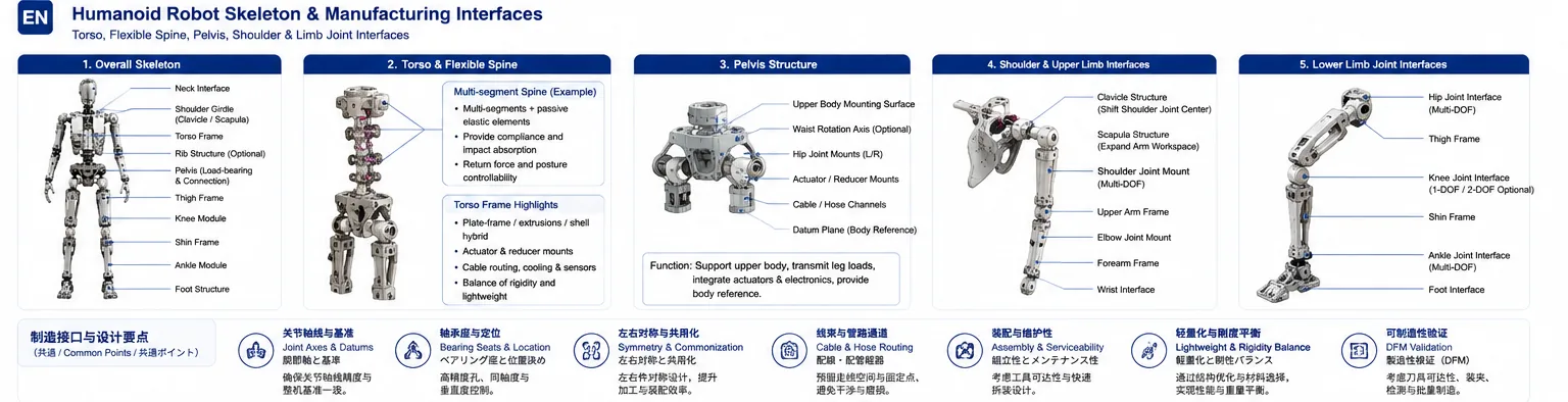
Humanoid skeleton architecture covering the torso, flexible spine, pelvis, shoulder, arms and lower limbs, with key joint, datum, bearing and routing interfaces.
1. Why Mass Distribution Matters More Than Total Mass
The same kilogram has a different effect near the pelvis than near the ankle. Mass farther from a joint axis increases rotational inertia and requires more torque and energy during acceleration and braking.
Lightweight design should first:
- reduce mass in shins, forearms, feet and other distal locations;
- place heavy actuators, batteries and computers closer to the torso or pelvis;
- shorten unnecessary cantilevers;
- avoid large cosmetic envelopes that do not carry load;
- create direct load paths without restricting joint range.
Dynamic humanoids need both stiff structures and suitable mass-inertia distribution. Some leg architectures place heavy actuators closer to the body and transmit force distally through links or mechanisms specifically to reduce swing inertia.
2. The Skeleton Is a Multi-Interface Load System
2.1 Torso Frame
The torso is both the upper-body structural frame and the platform for batteries, computers, networking, sensors and shoulder modules. It must resist:
- arm-generated torsion;
- inertial loads from waist acceleration;
- forward bending while handling payload;
- fall and collision impact;
- packaging constraints from cooling, electronics and cables.
Common forms include box frames, side plates with cross-members, extruded frames, thin-wall shells and metal-polymer hybrids.
2.2 Pelvis Frame
The pelvis is a major load junction. It connects the waist, both hips, actuators, sensors and cable routes while maintaining bilateral kinematic symmetry.
Key considerations include:
- hip-axis location and parallelism;
- relationship between waist and leg datums;
- peak hip torque and impact;
- actuator installation and removal;
- cable routing without motion interference;
- center of gravity and total mass distribution.
2.3 Limb Frames
Thighs, shins, upper arms and forearms must be light while remaining stiff enough to prevent bending and torsion from creating end-effector error. They usually emphasize stiffness per unit mass and low inertia more than the torso.
3. Human-Inspired Does Not Mean Copying Bones: Design Stiffness, Compliance and Controllability Together
Traditional industrial robots prioritize stiffness, accuracy and speed. In homes, service environments and frequent human contact, safety, adaptability and physical compliance become more important. The value of human inspiration is not to reproduce every bone, but to understand how segmented structures, passive elasticity, multi-joint tendons and distributed deformation absorb impact and adapt to uncertain environments.
3.1 A Segmented Spine Distributes Large Motion Across Small Joints
The human spine is not one large hinge. Many small motion segments create the overall posture, while discs, ligaments and tendons provide elasticity, restoring force and impact absorption.
A robot can translate this idea into:
- modular vertebral or waist segments;
- elastomers, springs or flexures for passive return;
- tendons, cables or links spanning multiple joints;
- limits, preload and damping for extreme posture;
- distributed sensing and calibration.
The cost is more assembly clearance, friction, wear, cable motion and pose-estimation error. Elastomer hardness, preload, inter-segment clearance, bore alignment, limit position and assembly repeatability must become CTQs rather than checking only the dimensions of each segment.
3.2 Scapula-Clavicle Thinking Moves the Shoulder Center
The human shoulder is not a simple ball joint fixed to the torso. Scapula and clavicle motion changes the shoulder center relative to the rib cage, enlarging arm reach and creating internal space for actuators and equipment.
For humanoid design this can:
- expand forward reach, overhead reach and cross-body motion;
- place parts of the shoulder mechanism outside the torso volume;
- distribute load through a wider shoulder girdle;
- reduce cover interference by moving the joint center.
More degrees of freedom are not automatically better. Research prototypes that closely copied the human scapula could become difficult to control because the posture was not unique. Constraining scapular motion to a designed surface or guide path can produce more predictable behavior.
3.3 Nominal Joint Range Is Not Usable Robot Range
Usable motion is limited by axis placement, link section, covers, cables, fasteners, soft stops and assembly clearance. A joint with a large rated angle can lose much of that range after installation.
A practical modeling example gives two useful reminders:
- an extra shoulder connection can enlarge forward reach;
- a two-axis or double-joint knee can avoid early thigh-shin interference and increase folding range.
These are not universal production solutions. Every added joint increases mass, bearings, cables, tolerance stack and control complexity. The correct sequence is:
Required task workspace → full-body envelope and interference study → architecture comparison → prototype validation → minimum necessary freedom
4. From Concept Skeleton to a Durable Engineering Structure
A convincing skeleton model is still far from a robot that can operate repeatedly. Mature development advances mass, center of gravity, dynamics, structural testing, material joints, covers, serviceability and electronics packaging together.
4.1 Build the Mass, Center-of-Gravity and Joint-Load Model First
Before detailed structure, estimate:
- complete robot and module masses;
- center of gravity and link inertias;
- walking, squatting, carrying and fall poses;
- required joint angle, speed and peak torque;
- friction from covers, seals, cables and soft skins.
An engineering development example first estimated finished mass, motion speed and equipment layout, then used a dynamic model to calculate joint angles, torque and speed, including cover-friction load in the final actuator requirement. This sequence prevents discovering too late that motors, reducers or bearings are undersized.
4.2 Calibrate Material Data with Physical Tests
The real behavior of composites, bonded structures and additive parts varies with layup, fiber direction, wall thickness, holes and manufacturing lot. Handbook modulus should not be inserted into FEA without verification.
A stronger route is:
- manufacture coupons with the intended section and process;
- run bending, tension/compression or torsion tests;
- derive effective stiffness from load-displacement data;
- calibrate the structural model;
- determine section, wall and reinforcement;
- confirm correlation at component and full-system level.
“Simulation first” must therefore include “test-calibrated.” A fine mesh cannot compensate for an inaccurate material model.
4.3 Treat Hybrid Interfaces as Designed Components
A published internal-frame robot used CFRP tubes for long load paths, machined aluminum gearboxes at joints, and bonded the two; composite feet also reduced leg inertia. This “light member + precise metal interface” approach is relevant to humanoids, but the joint is often the highest-risk area.
Control:
- composite-end geometry and fiber integrity;
- bond length, groove geometry and fillets in the metal fitting;
- abrasion, cleaning, primer and open time;
- bondline thickness, cure temperature, pressure and time;
- galvanic isolation between carbon fiber and metal;
- thermal-expansion mismatch and cyclic load;
- pull-out, torsion, fatigue and nondestructive inspection.
The interface is not “apply adhesive during assembly.” It needs drawings, a process window, qualification and lot traceability.
4.4 Full-Scale Mockups Reveal Interference and Service Problems Hidden in CAD
The frame, cover, soft skin, harness and electronics are often developed by different teams. CAD alone cannot fully predict wrinkles, friction, removal paths or real access.
Useful tools include:
- full-scale or low-cost skeleton mockups;
- physical covers and soft-skin samples;
- 3D scanning of hand-shaped geometry back into CAD;
- full-range interference, friction-torque and cable-bend checks;
- quick-access validation at shoulders, abdomen and battery areas;
- cooling openings and internal thermal-management checks.
A full-scale mockup lets structure and covering progress in parallel and exposes interference before expensive tooling. Production design should make frequent-service areas quick-release modules instead of requiring removal of the entire cover.
4.5 Commonality and Modularity Are Production Metrics
Part commonality across left/right limbs or robot variants can reduce:
- drawing and process count;
- fixture, tool and gauge investment;
- spare inventory;
- training and assembly errors;
- change-validation work.
Commonality must not ignore real load and packaging differences. Interfaces, bearing sleeves, fasteners, sensor brackets and local modules are good candidates; parts with different load direction, harness routing or service space may still require mirrored or dedicated designs.
5. Selecting the Structural Architecture
| Architecture | Advantage | Main risk | Typical stage |
|---|---|---|---|
| Monolithic CNC frame | Accurate interfaces, high stiffness, easy iteration | High material removal and complex cavities | Prototype, low volume, high-precision interfaces |
| Plates with spacers/cross-members | Fast development, modular service | More parts, fasteners and stack-up | Research platforms and modular products |
| Two-piece shell | Good internal access and cable routing | Joint stiffness, location and sealing | Torso, pelvis and limb shells |
| Casting/forging plus machining | Good material use and scalable volume | Tooling, defects and distortion | Stable medium/high-volume design |
| Extrusion or tube | Lightweight, stable supply and low cost | Limited local interfaces | Torso rails and long limb members |
| Sheet-metal or welded box | Efficient for enclosures | Weld distortion and fatigue | Internal torso supports and guards |
| Additive manufacturing | Complex load paths and integrated features | Consistency, finish, dimensions and cost | Complex prototypes and local light parts |
| Metal-composite hybrid | Low mass and high specific stiffness | Joining, thermal expansion and repair | Premium distal limbs and covers |
A production robot will usually combine several routes: machined metal at precision joints, extrusions or composites for long load paths, and polymers or additive parts for cable and protective functions.
6. Topology Optimization Is Not the Final Part
Topology optimization helps identify:
- where material must remain;
- dominant tension, compression, bending and torsion paths;
- regions that can be lightened;
- trade-offs among multiple load cases.
The raw result may contain irregular surfaces, thin branches, closed cavities, undercuts and abrupt wall changes. Production reconstruction must:
- preserve the main load paths;
- create controlled wall thickness;
- add continuous fillets at stress transitions;
- define machining, assembly and inspection datums;
- provide tool access, chip evacuation and cleaning;
- remove inaccessible cavities;
- reinforce threads, bearing seats and dowel areas;
- repeat static, modal, fatigue and tolerance validation.
Weight normally decreases after optimization, but stiffness, natural frequency and stress also change. The result must be evaluated against control bandwidth, impact, life and manufacturing variation.
7. Assigning Materials by Skeleton Region
| Material | Suitable region | Strength | Main concern |
|---|---|---|---|
| 6061 aluminum | Torso, pelvis and general limb frames | Balanced machining, joining, finish and cost | Local strength and thread life |
| 7075 aluminum | High-load thigh, pelvis and reinforcements | High specific strength | Joining, corrosion and stress cracking |
| Magnesium alloy | Distal limbs and light shells | Very low density | Corrosion, process safety and finish |
| Titanium alloy | High-load connectors, inserts and thin critical parts | High specific strength and corrosion resistance | Cost, machining and galling |
| Stainless/alloy steel | Bearing sleeves, threaded inserts, pins and wear interfaces | Strength and wear resistance | High mass and galvanic compatibility |
| CFRP composite | Long limbs, covers and high-specific-stiffness members | Low mass and high specific stiffness | Metal joints, drilling and repair |
| Engineering polymer / AM polymer | Cable carriers, trays and non-primary covers | Fast integration and development | Creep, temperature, impact and life |
The practical answer is rarely “all aluminum” or “all carbon fiber.” Materials should be zoned by load, interface, serviceability and production economics.
8. Joint Interfaces Are the Main CTQs
The interface between the frame and actuator defines kinematic accuracy. Important features include:
- bearing bores and faces;
- motor, reducer and output-flange mounts;
- bilateral joint datums;
- dowel and threaded holes;
- encoder and zero-calibration features;
- cable passages and edge protection;
- cover and impact-guard mounts.
| CTQ | Failure effect | Recommended control |
|---|---|---|
| Joint-axis position | Kinematic model error and gait asymmetry | Unified datum and CMM inspection |
| Axis parallelism/perpendicularity | Binding, friction and control error | One setup or verified datum transfer |
| Bearing-seat coaxiality | Bearing overload, noise and short life | Finish boring and fit verification |
| Mounting-face flatness | Actuator tilt and uneven bolt load | Finish machining and free-state inspection |
| Left/right mirror consistency | Bilateral parameter mismatch | Paired inspection and digital traceability |
| Thread and insert location | Assembly failure or rework | Gauging, pull-out and position checks |
| Assembly mass and center of gravity | Dynamic-model error | Weighing and mass-property control |
9. Why Thin-Wall Frames Distort
Lightweight frames use deep pockets, ribs and thin walls. As material is removed, residual stress, fixture load and cutting heat rebalance and the part moves.
Typical risks include:
- wall spring-back after roughing;
- mounting-face warp after unclamping;
- opposite distortion in mirrored parts;
- uneven deep-pocket floor thickness;
- dimensional change after anodizing, coating or heat treatment;
- forced flattening during assembly that stores residual stress.
A practical route is:
- select stable material condition and stock orientation;
- remove material symmetrically;
- include stress relief or natural aging after roughing;
- machine datums, pockets and interfaces in stages;
- use low-distortion fixtures with adequate support;
- inspect flatness and axes in the free state;
- recheck CTQs after surface treatment;
- use prototype distortion data to tune stock allowance.
10. Assembly Datums Matter More Than Isolated Dimensions
A skeleton is assembled from multiple parts and joint modules. Every individual dimension can pass while the full robot axis chain is still incorrect.
Use three datum levels:
- robot datums: foot sole, pelvis center and torso centerline;
- module datums: left/right hip, shoulder, knee and ankle modules;
- part datums: bearing bores, faces, dowels and holes.
The tolerance chain should cover:
- sole to ankle axis;
- ankle to knee;
- knee to hip;
- distance between left and right hip axes;
- pelvis to waist center;
- shoulder axes and bilateral arm symmetry.
Mirrored parts should use the same program logic, datum strategy and paired inspection to avoid systematic left-right differences.
11. Validation Must Go Beyond Static Load
| Validation | Purpose |
|---|---|
| Static and limit load | Strength, displacement and safety margin |
| Modal analysis and vibration | Keep resonance away from motion/control bands |
| Fatigue | Repeated walking, arm motion and payload cycles |
| Fall and collision | Impact path, local yield and repairability |
| Maximum joint torque | Bearing, bolt and interface stiffness |
| Thermal deformation | Motor, battery and computing heat |
| Mass, CoG and inertia | Real inputs for dynamics and control |
| Cable motion and wear | No pulling, pinching or interference |
| Protection and service | Inspection, replacement and recovery after impact |
Validation should use the assembled condition with actuators, batteries and cables. An empty frame does not fully represent the final loads or modal behavior.
12. From Prototype to Production
- 01Define Loads and InterfacesJoint torque, mass distribution, fall cases, datums and service space.
- 02Compare ArchitecturesCNC, plate frame, shell, casting, extrusion and hybrid concepts.
- 03Simulation and ReconstructionStatic, modal and topology studies converted into manufacturable geometry.
- 04Engineering PrototypeMachining distortion, joint interfaces, assembly sequence and cable paths.
- 05Full-Robot CorrelationMass, CoG, inertia, modal, fatigue and fall performance.
- 06Freeze Production ProcessStock, fixture, datum, tooling, inspection and surface treatment.
- 07Production MonitoringCTQs, distortion, mass properties and left-right pairing.
Production optimization includes reducing part count, standardizing bilateral modules, lowering assembly adjustment, improving inspectability and making likely impact-damage parts replaceable.
13. Information Required for RFQ and Engineering Review
| Information | Recommended content |
|---|---|
| 3D and 2D | Full model, revision, datums, CTQs and tolerances |
| Load cases | Joint torque, payload, fall, collision and safety factor |
| Mass target | Part mass, robot mass, CoG and inertia |
| Interfaces | Actuator, bearing, encoder, dowel, thread and cable |
| Material and finish | Material condition, heat treatment, anodizing, coating and inserts |
| Assembly | Left-right pairing, order, torque and service requirements |
| Validation | Static, modal, fatigue, fall and environment |
| Volume | Prototype, engineering lot, ramp and annual demand |
| Traceability | Serial, material lot, machining and inspection records |
| Change control | Drawing revision, deviation and revalidation |
Frequently Asked Questions
Should a humanoid robot skeleton always be made as light as possible?
No. Weight reduction must still satisfy stiffness, strength, modal, fatigue, fall-impact, joint-location and service requirements. Excessive thinning can cause axis drift, vibration, reduced control accuracy and life risk. The correct goal is to remove ineffective mass and reduce distal inertia.
Can topology-optimization output be machined directly by CNC?
Usually not. Topology optimization primarily indicates load paths and material-retention regions. Production design still requires reconstruction with consistent walls, fillets, datums, tool access, chip evacuation and fewer deep cavities or undercuts, followed by renewed static, modal and fatigue validation.
Should the torso, pelvis and limb frames use the same material?
Not necessarily. The torso and pelvis emphasize global stiffness, many interfaces and equipment support, while distal limbs prioritize low mass and inertia. Bearing seats and threaded interfaces require wear resistance and local strength. A common solution is an aluminum body with steel or titanium inserts, sometimes combined with magnesium, composites or additive structures.
What is the most important validation before humanoid-frame production?
The program should validate critical interface tolerance chains, static and limit loads, modal and vibration behavior, repeated-motion fatigue, fall or collision loads, mass and center of gravity, cable routing and service access, while also demonstrating stable machining, assembly and inspection capability.
