
In This Article
Direct Answer
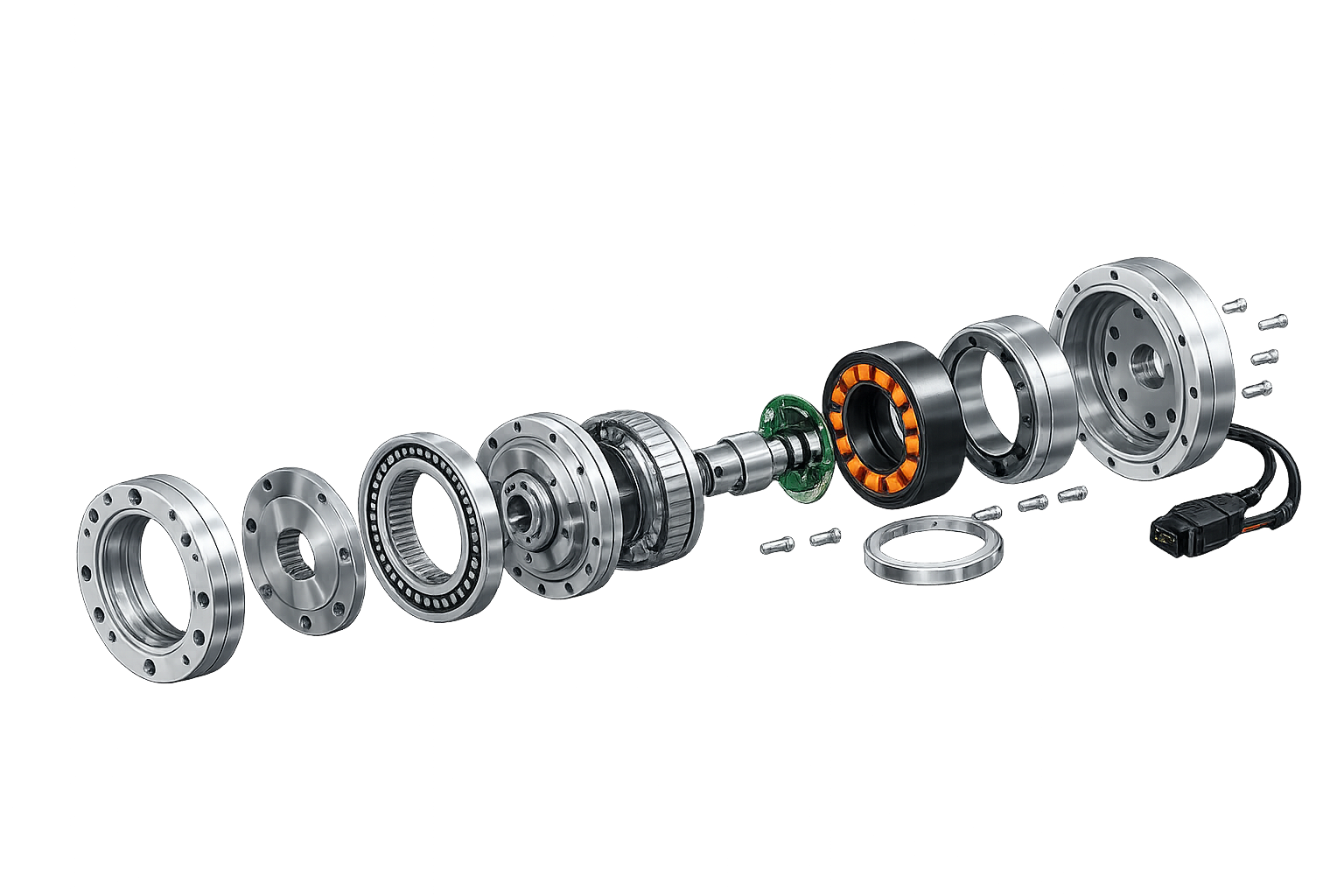
When a humanoid robot lifts a leg, balances its body, grips an object or reacts to an external impact, the control system does not move the arm or leg directly.
A command first reaches the drive electronics. The motor generates rotation, the transmission changes speed and torque, and the bearing and output structure transfer the load to the robot link. At the same time, encoders and sensors report position, speed, temperature or force back to the controller.
A joint actuator is therefore not simply a motor. It is an electromechanical system that must operate around one controlled joint axis.
A typical rotary joint actuator may include:
- a motor and drive electronics;
- a precision reducer;
- input-side or output-side encoders;
- a bearing system;
- an output shaft and output flange;
- cables, seals and connectors;
- an actuator housing that supports and locates the complete assembly.
The decisive issue is not the number of components. It is whether these components can maintain the correct axis, face relationships, fits and thermal path inside a compact package.
1. Start with the joint task, not the actuator catalogue
A humanoid robot may use dozens of joints, but each joint performs a different mechanical and control task. Using one actuator design everywhere usually creates unnecessary compromises.
| Joint | Main task | Actuator priorities |
|---|---|---|
| Hip | Support the body, drive the whole leg, shift the centre of mass | Continuous torque, structural stiffness, thermal performance, power density |
| Knee | Carry load, absorb impact, flex and extend rapidly | Balance of torque and response, backdrivability |
| Ankle | Interact with the ground, correct posture, maintain balance | Control bandwidth, fast feedback, position and force control |
| Shoulder | Large-range motion and load support | Output capability, weight, range of motion |
| Elbow | Rapidly reposition the arm | Low inertia, compactness, dynamic response |
| Wrist and hand | Fine manipulation and compliant contact | Miniaturisation, accuracy, feedback and dexterity |
A hip actuator normally places greater emphasis on continuous output and heat dissipation. A knee repeatedly switches between load support, acceleration, deceleration and impact. An ankle may not require the highest peak torque, but it often needs faster and more precise feedback control.
The correct starting question is therefore not “Which motor has the highest torque?” but:
Under what load, speed, space and temperature conditions will this joint operate? Does it need force, response, precision or compliance most?
2. Understand the actuator through two paths
Instead of memorising parts from left to right, follow the two functional paths inside the assembly.
Torque path
Control command
→ Drive electronics
→ Motor
→ Reducer
→ Output flange
→ Robot link
Feedback path
Joint position, speed, load and temperature
→ Encoder / sensors
→ Control system
→ Current, speed and torque correction
The internal architecture of the actuator must protect both paths within a limited volume.
3. What does each component do?
3.1 Drive electronics and control components
The drive receives a target position, speed or torque command from the robot controller and regulates motor current. Modern joint modules increasingly integrate the motor, encoder, drive electronics and communication interface inside one housing to reduce external wiring and installation space.
Integration also concentrates heat, reduces available cable space and makes assembly and servicing more dependent on sequence. Mechatronic integration is therefore not simply a matter of putting more parts into one enclosure. The load path, heat path, cable path and maintenance path must be designed together.
3.2 Motor
The motor converts electrical energy into rotation. A humanoid joint motor usually has to balance:
- peak and continuous torque;
- rotor inertia;
- response speed;
- energy efficiency;
- temperature rise and heat dissipation;
- stable long-duration operation.
Peak torque alone can be misleading. An actuator that produces a high torque for a few seconds may still be unsuitable for continuous walking, standing or load carrying.
3.3 Encoders and sensors
Encoders measure motor-side or output-side position and speed. Depending on the control architecture, the actuator may also include dual encoders, torque sensors, temperature sensors and current monitoring.
These devices tell the controller where the joint is, how much resistance it is experiencing and whether it is overheating. A displaced encoder mounting face, magnetic ring seat or read-head reference can lead to zero-offset error, control oscillation or poor repeatability even when the mechanical assembly still rotates.
3.4 Precision reducer
Motors usually run at higher speed than a robot joint requires. A reducer lowers speed and increases output torque. Possible architectures include strain-wave, planetary, cycloidal and quasi-direct-drive systems.
A higher reduction ratio is not automatically better. It can increase output torque, but it may also add friction, reflected inertia and resistance to backdriving. A lower ratio can improve response and compliance, while increasing the motor load.
Reducer selection must consider torque, speed, shock load, efficiency, noise, life and backdrivability rather than rated torque alone.
3.5 Bearing system
Bearings do more than allow rotation. They may carry radial load, axial load, overturning moment, assembly preload and external impact.
A loose bearing seat can create clearance and vibration. An excessively tight seat can alter preload, increase friction and raise temperature. In compact housings, weight-reduction pockets, bolt holes and thin walls are often located near bearing seats, making roundness, shoulder rigidity and post-machining stability more difficult to maintain.
3.6 Output shaft and output flange
The output flange connects the actuator to the robot link. It transfers torque while also providing location, bolt attachment, dowel-based repeatability and resistance to axial and overturning loads.
If the output flange is misaligned with the bearing axis, individual diameters may still pass inspection while the assembly develops face runout, uneven rotational resistance or eccentric loading.
3.7 Actuator housing
The housing may look like an aluminium enclosure, but it serves three distinct roles:
| Role | Function |
|---|---|
| Load-bearing structure | Carries the motor, reducer, bearings and external loads |
| Locating datum system | Establishes coaxiality, perpendicularity and positional relationships |
| Functional carrier | Integrates cable routing, sealing, heat transfer, mounting and service features |
The housing is not merely a protective cover. It is the mechanical datum system of the actuator.
4. The machining priority is the joint axis, not the outer profile
An actuator housing may contain multiple bores, shoulders, faces, threaded holes and mounting interfaces. Each feature can be within its individual size tolerance while the assembled actuator still suffers from:
- bearing binding;
- motor-to-reducer misalignment;
- eccentric reducer loading;
- output runout;
- vibration, noise or local overheating;
- position change after repeated disassembly.
The reason is that actuator accuracy is created by a network of related features, not by one dimension.
Machining planning should first define the datum axis that controls joint rotation, then relate the following features to that axis:
Bearing seats
↕
Reducer pilot
↕
Motor mounting face
↕
Encoder mounting feature
↕
Output shaft / output flange
↕
Seal groove and cover interface
Only after the motion-controlling bores and faces are identified can workholding, roughing, semi-finishing, finish boring, surface treatment and final inspection be planned correctly.
5. Screws clamp; locating features create repeatability
Screws normally secure the motor, reducer, covers and output structure. Their main function is to generate clamping force, not precision location.
Repeatable or high-accuracy assembly generally relies on:
- locating pilots;
- precision dowel holes and dowel pins;
- fitted shoulders;
- datum faces.
This is especially important during prototype development, when an actuator may be opened repeatedly to replace a reducer, encoder, cable or bearing. If each rebuild depends on clearance in bolt holes, the test results may include an uncontrolled assembly-position change.
The drawing should distinguish clearly between:
Features used for clamping
≠
Features used for location
6. Lightweight design does not mean making every wall thin
A humanoid robot contains many joints, so any mass reduction in one actuator is multiplied across the machine. Lightweight actuator and housing design is therefore important.
However, reliable lightweighting begins with the load and torque path:
Robot link
→ Output flange
→ Bearings and reducer
→ Load-bearing housing region
→ Adjacent robot structure
Pockets, ribs and scallops can be placed in non-critical regions, while sufficient material should remain around:
- bearing seats;
- output flange interfaces;
- reducer locating features;
- dowel holes and bolt circles;
- housing mounting interfaces;
- primary torque-transfer paths;
- transitions between thin and thick sections.
Thin aluminium housings can move as residual stress is redistributed after rough machining. Some designs therefore require:
Rough machining
→ Stabilisation or stress-relief interval
→ Semi-finishing
→ Finish machining of critical bores and faces
→ Final inspection
Effective lightweighting reduces mass without sacrificing stiffness, alignment or process stability.
7. The housing is part of the thermal path
Heat can be generated by motor copper and iron losses, reducer friction, bearing friction and power electronics.
The housing may provide:
- motor stator mounting and heat conduction;
- a heat path from the drive electronics;
- external convective cooling area;
- internal thermal separation;
- temperature-sensor mounting;
- integrated cooling features or channels.
A motor mounting face that is not flat, or that has insufficient effective contact area, can affect both alignment and heat transfer into the housing. Flatness, contact condition and surface-finish requirements may therefore be mechanical and thermal requirements at the same time.
8. Cable channels are an easy failure point to overlook
A compact joint can carry motor power cables, encoder wires, sensor leads and communication lines. Some designs also include cooling lines. These elements repeatedly bend as the joint moves.
A small burr, sharp edge or unsuitable bend radius can gradually damage insulation. Cable channels should therefore be reviewed for more than simple geometric clearance:
- Can the cutting tool reach the feature?
- How will hidden burrs be removed?
- Are exits blended with suitable radii?
- Can the harness contact a rotating component?
- Can the internal path be observed during assembly and inspection?
For channels that cannot be inspected directly, deburring and inspection expectations should be defined during RFQ and engineering review, not after assembly problems appear.
9. Surface treatment is not merely a final cosmetic step
Aluminium actuator housings are often anodised or hard-anodised for corrosion resistance, wear resistance and appearance. The coating also changes functional dimensions.
Critical areas can include:
- bearing fits;
- reducer pilots;
- dowel holes;
- motor contact faces;
- seal grooves;
- electrical grounding pads;
- threads;
- precision assembly faces.
| Area | Typical control approach |
|---|---|
| Bearing seats and precision bores | Masking, allowance compensation or post-treatment finishing |
| Dowel holes | Masking or final-size control |
| Sealing faces | Control of coating, scratches and local defects |
| Electrical grounding pads | Local masking |
| Cosmetic surfaces | Colour, rack marks and handling damage control |
| Threads | Allowance, masking or post-treatment verification |
A surface finish is not acceptable merely because the colour is uniform. The treated part must still assemble and function correctly.
10. Which housing features should receive the most inspection attention?
High-quality inspection does not mean applying equal measurement effort to every dimension. The first step is to identify the critical characteristics that directly control actuator performance.
| Critical characteristic | Potential problem | Typical inspection method |
|---|---|---|
| Bearing-seat diameter | Loose fit, excessive interference, preload change | Bore gauge, air gauge |
| Roundness and cylindricity | Uneven resistance and local loading | Roundness equipment or a suitable metrology method |
| Coaxial relationship of bearing seats | Binding, vibration, output wobble | CMM, master mandrel and runout check |
| Motor-face flatness | Poor contact, misalignment and reduced heat transfer | CMM or flatness inspection |
| Perpendicularity to joint axis | Motor and reducer axis error | CMM |
| Reducer pilot | Eccentric assembly and uneven load | CMM, bore or outside-diameter gauges |
| Dowel-hole position | Reduced assembly repeatability | CMM |
| Output-face runout | Link wobble and eccentric loading | Runout inspection |
| Seal-groove geometry | Leakage or incorrect seal compression | Depth and profile inspection |
| Burrs in cable channels | Cable insulation damage | Visual, borescope or dedicated inspection |
| Post-treatment fit dimensions | Assembly failure or changed fit | Post-treatment reinspection |
A housing can look excellent and still fail if its joint axis and critical mounting interfaces are incorrect.
11. What should be included in an RFQ?
A 3D model alone rarely communicates the full manufacturing intent of an actuator housing. For a more accurate engineering review and quotation, provide:
- 2D drawings and 3D models;
- material grade and condition;
- the joint centre axis and primary datums;
- bearing, reducer, motor and encoder interface requirements;
- critical fits, dimensional tolerances and GD&T;
- surface treatment and masking areas;
- cable-channel deburring requirements;
- inspection-report and measurement requirements;
- prototype quantity, development stage and expected production volume;
- any required subassembly or fit verification.
A serious manufacturing review should move beyond “What material, tolerance and quantity?” and ask:
Which axis controls motion? Which faces locate the assembly? Which features transfer torque? Which dimensions must remain after surface treatment? How will the part be assembled and inspected?
These questions separate the machining of a shape from the manufacture of a stable robot-joint component.
Conclusion: actuator performance comes from the system
The motor creates power, the reducer changes speed and torque, the encoder supplies feedback, the bearings support load and the drive electronics control motion.
These components only create a stable joint when they work within the correct axis, mounting-face and assembly relationships.
The value of the actuator housing is not simply that it contains the components. It organises:
Motor axis
+ Reducer axis
+ Bearing axis
+ Output axis
+ Encoder datum
+ Robot mounting interface
into a precision system that can be manufactured, assembled, inspected and reproduced consistently.
In actuator structural-component reviews, Zhongde focuses on relationships between critical interfaces, datum planning, thin-wall distortion, surface-treatment compensation and final measurement strategy—not only whether the outer shape matches the 3D model.
For prototype, low-volume validation or production-introduction projects involving actuator housings, reducer locating seats, output flanges or encoder mounting structures, clearly marking the joint axis, critical fits, surface treatment and inspection requirements helps establish a more reliable manufacturing and quality-control plan.
Frequently asked questions
What is the difference between a humanoid robot actuator and a motor?
The motor is the power-generating component. A complete joint actuator usually also includes a reducer, bearings, encoders, drive electronics, output structure, housing, cables and seals.
Why can the same actuator not be used for every joint?
Different joints perform different load and motion tasks. Hip joints place greater emphasis on continuous torque and thermal performance, knees require a balance of torque and dynamic response, and ankles depend more strongly on fast feedback, precision and response to external forces.
What is the most important machining accuracy in an actuator housing?
One bore diameter alone is not enough. The relationship of bearing seats, reducer location, motor faces, output interfaces and encoder features to the common joint axis is more important.
Can anodising affect bearing and dowel holes?
Yes. The coating changes real fit dimensions, so precision bores, dowel holes, seal faces and grounding pads may require masking, allowance compensation or post-treatment machining.
Is a 3D model sufficient for quotation?
It can support an initial review, but an accurate quotation normally also requires 2D drawings, material condition, critical tolerances, datums, surface treatment, inspection requirements and expected quantity.
