
In This Article
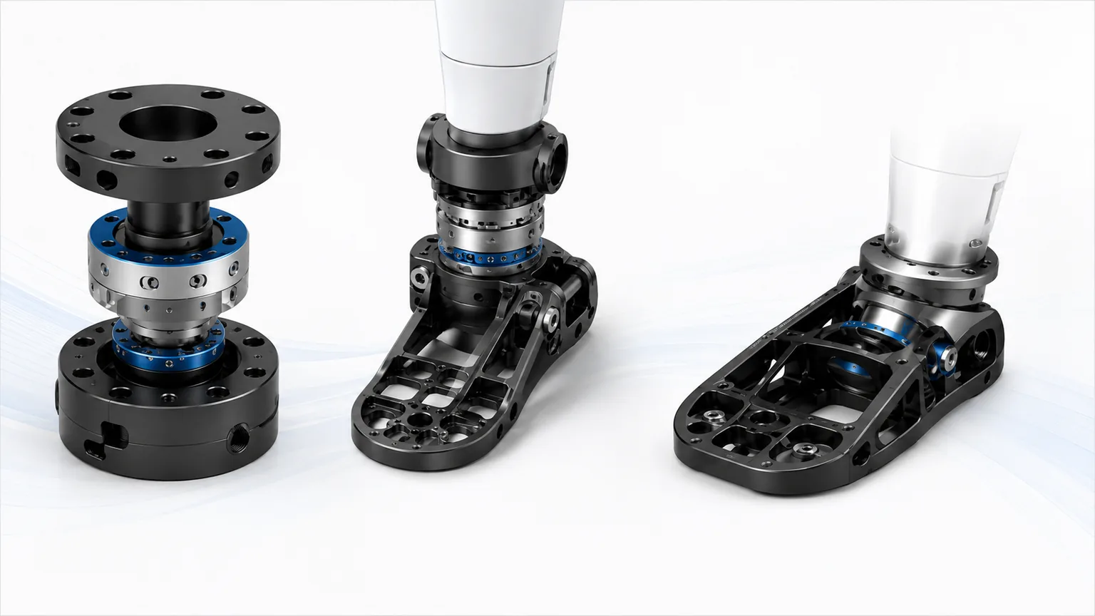
Direct Answer
The humanoid foot is the junction of four systems:
- Structure: carries robot mass, ground reaction, push-off and impact;
- Motion: connects ankle actuators, bearings, reducers and the shin;
- Sensing: supports six-axis force sensors, pressure sensors or tactile arrays;
- Ground contact: uses sole material, shape and compliance to interact with the floor.
The manufacturing goal is not to copy the visual shape of a human foot. It is to make load, sensing, friction and deformation predictable.
| Module | Function | Manufacturing focus |
|---|---|---|
| Ankle interface | Transfer pitch, roll and axial loads | Axes, bearing seats, flanges and faces |
| Force-sensor region | Measure ground force and moment | Flatness, parallelism, location and preload |
| Main foot frame | Distribute load and maintain geometry | Thin walls, ribs, stiffness and distortion |
| Forefoot / heel | Contact, push-off and impact attenuation | Segment stiffness, elastic element and stops |
| Sole / contact pad | Friction, wear protection and damping | Material, thickness, texture and replacement |
| Cable and guards | Protect sensor cables and connectors | Bend radius, pinch protection and service |
1. Why the Foot Is Central to Robot Control
During standing and walking, the controller must determine:
- whether and where the foot has contacted the ground;
- ground reaction force and moment;
- center-of-pressure location;
- slip, heel/toe lift or edge contact;
- slope, step or local unevenness;
- whether impact exceeds the allowable boundary.
Mechanical deformation, eccentric sensor mounting and sole compression all affect these estimates. Mechanical structure and sensor calibration must therefore be developed together.
2. Rigid, Compliant and Segmented Foot Architectures
| Architecture | Advantage | Main risk | Typical use |
|---|---|---|---|
| Rigid monolithic foot | Stable geometry and simple model | Direct impact and limited terrain adaptation | Flat floors and early development |
| Compliant sole layer | Simple impact and friction improvement | Aging, compression set and temperature sensitivity | General industrial movement |
| Segmented forefoot/heel | Better push-off and edge adaptation | More joints, stops and tolerance stack | Natural gait and uneven ground |
| Spring/elastomer arch | Absorbs ground reaction and protects sensing | Stiffness variation, hysteresis and fatigue | Higher impact and passive adaptation |
| Multi-point tactile foot | Detects local contact and terrain | Packaging, wiring and calibration complexity | Advanced terrain adaptation |
Research foot structures have used longitudinal and transverse arches, passive joints or springs to absorb ground reaction and protect force sensors. Compliance must still have predictable stiffness, return and mechanical stops so that it does not create an uncontrolled state.
3. An Idealized Foot in a Control Model Is Not a Manufacturing Specification
Biped-control studies often idealize the foot to reduce computational complexity. One planar model assumes zero foot mass, full-sole contact, infinite friction and perfectly inelastic touchdown, and represents gait through left support, right support and impact-transition modes.
These assumptions are useful for control and trajectory research, but they cannot be copied into physical requirements. A real foot has:
- nonzero mass and rotational inertia;
- heel, toe, edge and partial-contact events;
- finite friction that changes with sole, dust, oil and floor material;
- structural compliance, damping, rebound and possible permanent set;
- support-mode switching based on sensors and state estimation;
- ankle torque, sole deformation and installation errors that affect the model.
Mechanical, sensing and control teams should maintain a model-to-hardware parameter map.
| Model simplification | Physical measurement or validation |
|---|---|
| Massless foot | Foot mass, center of gravity and ankle-axis inertia |
| Instant full-sole contact | Heel, toe, edge and local contact sequence |
| Infinite friction | Static and dynamic friction across floors and contamination |
| Perfectly inelastic collision | Impact peak, contact time, rebound and damping |
| Instant support-mode switch | Detection threshold, delay, chatter and false state |
| Rigid link | Load deformation of sole, sensor plate and ankle |
The value of the simplified model is to reveal the parameters that hardware must provide, not to force the hardware to behave like an ideal assumption.
4. Variable-Curvature Soles Require Shape, Stiffness and Contact Validation
A flat sole supports area contact, stable standing and intuitive force control. A curved sole can roll over the ground and shift the contact point. Research prototypes have changed the sole from flat to an arc during operation so that the robot can choose between stable standing and rolling behavior.
This exposes an important trade-off:
A more flexible sole needs less actuation to change shape but deforms more under ground reaction; a stiffer sole holds geometry better but requires more actuation to change curvature.
A research mechanism improved loaded stiffness and curvature repeatability by changing how an elastic plate was supported and pushed. A production program should validate:
| Item | Recommended validation |
|---|---|
| Target curvature | Actual profile and repeatability at several commands |
| Loaded stiffness | Toe, midfoot, heel and lateral deflection |
| Actuation force | Load across curvature, temperature and life |
| Return and hysteresis | Difference between increasing and decreasing curvature |
| Mechanical limits | Safe boundary under overload, power loss and control fault |
| Wear and fatigue | Elastic plate, flexure, slider and joint life |
| Bilateral match | Left-right curvature, stiffness and response |
A contact sensor on a deformable sole should conform to the curved surface, provide adequate spatial resolution, remain light and thin, avoid protrusions that disturb rolling, and tolerate repeated sole deformation. Packaging, wire exit and adhesive thickness are part of the sole geometry.
5. Mechatronic Lessons from Powered Prostheses and Full-Scale Humanoids
Powered prostheses and humanoid robots serve different users, but powered prostheses face particularly strict distal-mass, detection, energy and fail-safe constraints.
5.1 Distal Modules Must Be Compact, Light and Responsive
A powered prosthesis integrates motors, drive electronics, angle sensing, inertial sensing, force sensing and a battery in a constrained package. The same lesson applies to humanoids: optimize the complete distal module, including electronics, harnesses, connectors, guards and battery contribution, not only the machined frame.
Level walking emphasizes speed and state transitions, while rising, stairs and heavy loading demand higher torque. Motor, reduction, elastic elements and thermal design should be selected against a task spectrum rather than one peak number.
5.2 Contact and Motion-Intent Detection Must Be Reliable
Powered-prosthesis control must detect when the user starts a step, lands or changes activity. A humanoid foot likewise uses contact signals for support transition, impact control and fault protection.
Validate:
- threshold drift with sole, temperature and zero;
- separation of heel, toe and full contact;
- delay relative to touchdown control;
- diagnosis of disconnection, saturation and sensor fault;
- recalibration after sole replacement or reassembly.
5.3 Power Loss Must Lead to a Predictable State
Safety cannot depend entirely on continuous power. Powered-prosthesis development has emphasized preserving useful passive behavior when the battery is unavailable. For a humanoid foot, the corresponding principles are:
- no uncontrolled free fall after power loss;
- predictable brake, stop and elastic-element state;
- no dangerous sole curvature or locked geometry after actuator failure;
- degraded or shutdown mode after force-sensor failure;
- safe release of preload during service.
5.4 Toe Freedom and Foot Force Sensing Are System Options
A full-size research humanoid used ankle pitch and roll, an additional toe-pitch axis, and foot force sensing for ZMP detection. This demonstrates that toe articulation and foot force sensing can participate directly in gait and posture control.
An added toe joint also adds bearings, actuation, sealing, harnessing, mass, tolerance stack and service work. Compare:
- fixed toe;
- passive elastic toe;
- limited segmented forefoot;
- active toe axis.
Select by task benefit, energy, reliability and service cost rather than by degree-of-freedom count.
5.5 Close Problems Through Design–Evaluate–Improve Loops
A powered-prosthesis project emphasized rapid internal cycles of design, prototype, user evaluation and improvement. Humanoid-foot development benefits from the same short loop:
Machined sample → load test → sensor calibration → walking test → teardown → structural and parameter correction
Each iteration should retain revision, part mass, sole state, sensor ID, calibration coefficients, impact data and abnormal findings.
6. Define the Load Path Before Styling the Foot
A typical path is:
Ground contact → sole/compliant layer → foot frame → force sensor → ankle interface → shin frame
Evaluate:
- vertical support;
- fore-aft push and braking shear;
- lateral moment;
- toe or heel edge contact;
- single support;
- landing and fall impact;
- abnormal torsion when the foot is trapped.
The force sensor must sit in a clear load path. Covers, cable brackets or sole fasteners must not bypass the sensor, otherwise measured force will not represent the true ground reaction.
7. Critical Ankle-Interface CTQs
| CTQ | Failure effect | Control |
|---|---|---|
| Ankle-axis location | Kinematic and sole-angle error | Unified datum and CMM |
| Axis orthogonality/parallelism | Coupling, binding and friction | One setup or verified datum transfer |
| Bearing-seat coaxiality | Overload, noise and life loss | Finish boring and fit check |
| Output-flange runout | Foot wobble and sensor eccentricity | Face, pilot and assembly check |
| Mounting-face flatness | Uneven bolt load and frame twist | Free-state finish and measurement |
| Dowel-hole position | Reassembly shift | Reaming, position and insertion check |
| Left-right foot height | Pelvis tilt and control compensation | Paired inspection and traceability |
The ankle package is compact and must integrate actuators, reducers, bearings, sensors, cables and guards. Manufacturing datums should follow the joint axes and sole datum rather than cosmetic surfaces.
8. Why Six-Axis Force Sensors Can Be Distorted by Mounting
Six-axis sensors measure three forces and three moments. Their surrounding structure can dominate the final result.
Common error sources:
- nonparallel mounting faces;
- inconsistent bolt preload;
- overconstraint from dowels and bolts;
- eccentric loading;
- cable force entering the sensor;
- local bending of the foot frame;
- changed orientation or preload after service;
- thermal zero drift.
Recommended controls:
- finish upper and lower faces in one datum system;
- separate locating and clamping functions;
- specify bolt grade, sequence and torque;
- prevent cable side load;
- add overload stops or mechanical protection;
- check zero, axial loading and cross-axis coupling after assembly;
- recalibrate after sensor replacement.
9. Center-of-Pressure and Ground-Force Calibration
Sensor factory calibration does not guarantee installed accuracy. Mounting structure, sole deformation, bolt preload and bilateral variation change robot-level behavior.
Calibration should cover:
- several known loading points;
- different vertical loads;
- fore-aft and lateral shear;
- single and double support;
- independent left and right calibration;
- repeatability before and after service;
- temperature and long-term zero drift.
Research force-sensing shoes have used known whole-body configurations and ground-reaction conditions to estimate center of pressure and force calibration parameters. In production, reference fixtures, loading positions and software parameters should be tied to each serial number.
10. Foot Frame and Contact Surface
7.1 Main Frame
The main frame must maintain:
- sensor-region stiffness;
- sole geometry;
- threads, locating features and sole attachment;
- edge-contact bending and torsion resistance;
- inspectability and repairability after impact.
Common routes include monolithic CNC plates, ribbed pockets, upper/lower shells, plate-and-spacer assemblies, castings and forgings with finish machining.
7.2 Replaceable Sole
The sole is a wear part and should normally remain separate from the structural frame.
Control:
- friction and wear life;
- dry, dusty or oily floor conditions;
- fasteners that do not damage the sensor region;
- thickness consistency after replacement;
- avoidance of local hard spots;
- traceability of left/right sole replacement.
Material name alone is not enough to predict friction because texture and true contact area also matter.
11. Materials and Manufacturing Routes
| Area | Typical material/route | Main concern |
|---|---|---|
| Ankle housing | 6061/7075 aluminum or machined casting/forging | Strength, bearing interface and mass |
| Main foot frame | CNC aluminum, casting or plate frame | Stiffness, sole geometry and volume cost |
| Sensor adapter | Stable aluminum or steel | Flatness, threads and repeatability |
| Sleeves and pins | Alloy steel, stainless or titanium | Wear, strength and mass |
| Elastic element | Spring steel, elastomer or composite | Stiffness, hysteresis and fatigue |
| Sole | Rubber, polyurethane or composite pad | Friction, wear, temperature and contamination |
| Guard | Engineering polymer or thin metal | Impact, cable and service access |
Precision load-bearing, sensing, energy absorption and wear functions should usually be layered rather than concentrated in one complicated part.
12. Distortion of Thin Walls and Large Planes
The foot frame combines broad planes, deep pockets and local ribs. Typical risks are:
- sole warp;
- nonparallel sensor faces;
- spring-back after unclamping;
- opposite distortion in mirrored feet;
- dimensional change after anodizing or heat treatment;
- forced flattening that preloads the sensor.
A practical process is:
- stable stock condition;
- symmetric roughing and even stock;
- stress relief after roughing;
- staged machining of sole, sensor faces and ankle interface;
- multi-point low-distortion support;
- free-state flatness inspection;
- post-finish reinspection;
- zero and cross-axis check after sensor assembly.
13. Landing Impact and Fatigue Validation
| Validation | Purpose |
|---|---|
| Rated static load | Robot mass and single support |
| Peak joint torque | Ankle flange, bearings and bolts |
| Toe/heel edge load | Local bending and eccentricity |
| Landing impact | Load path, sensor protection and permanent set |
| Walking fatigue | Frame, elastic elements, threads and sole life |
| Slope and uneven floor | Edge contact and passive adaptation |
| Friction and slip | Contact reliability across floors |
| Fall protection | Connectors, cable and guards |
| Post-test inspection | Sole, axes, zero and calibration shift |
An undamaged sensor does not prove the structure is unchanged. After impact, inspect mounting faces, bolt preload, sole geometry and measurement zero.
14. From Prototype to Production
- 01Define Task and FloorSpeed, payload, slope, step, friction and impact.
- 02Select Foot ArchitectureRigid, segmented, compliant arch or tactile foot.
- 03Define Load and Sensor PathsRoute ground reaction through the sensor without bypass.
- 04Engineering PrototypeAnkle axis, faces, sole distortion, sole material and cables.
- 05Calibration and CorrelationCenter of pressure, force and cross-axis coupling.
- 06Impact and FatigueLanding, edge contact, cycling and service stability.
- 07Freeze ProductionDatums, fixture, torque, calibration fixture and traceability.
15. Information Required for RFQ and Engineering Review
| Information | Recommended content |
|---|---|
| Robot parameters | Mass, speed, gait, payload and floor |
| Ankle interface | Axes, actuator, reducer, bearing and flange |
| Foot geometry | Length, width, forefoot, heel and clearance |
| Load cases | Single support, push-off, edge, landing and fall |
| Sensor | Model, range, mounting, overload and calibration |
| Sole | Material, friction, thickness, wear and replacement |
| Materials/finish | Aluminum state, steel, elastomer and finish |
| Mass target | Foot mass, center and distal inertia |
| Validation | Static, impact, fatigue, friction and environment |
| Traceability | Part, sensor, calibration and assembly records |
Frequently Asked Questions
Should a humanoid robot sole be as rigid as possible?
No. High rigidity supports stable geometry and simpler control models, but an excessively rigid foot transmits landing impact directly into the force sensor, ankle and reducer. The design must balance positioning accuracy, impact absorption, terrain adaptation and predictable behavior.
Why are the mounting faces of a six-axis force sensor critical?
Flatness, parallelism, bolt preload and locating errors at the upper and lower faces can introduce zero drift, cross-axis coupling and reassembly variation. A highly accurate sensor can still give unreliable robot-level results when its mounting structure bends or loads it eccentrically.
Does an acceptable sole flatness guarantee stable standing?
No. Stability also depends on sole material, local contact, floor irregularity, structural deformation, center-of-pressure estimation, bilateral foot height and control. Sole flatness is only one manufacturing CTQ.
What should be validated before humanoid-foot production?
Validate static load, peak joint torque, landing impact, cyclic fatigue, sole friction, center of pressure and ground-reaction-force measurement, sensor calibration, left-right consistency, cable motion and replacement of wear and protective parts.
