
In This Article
Engineering answer
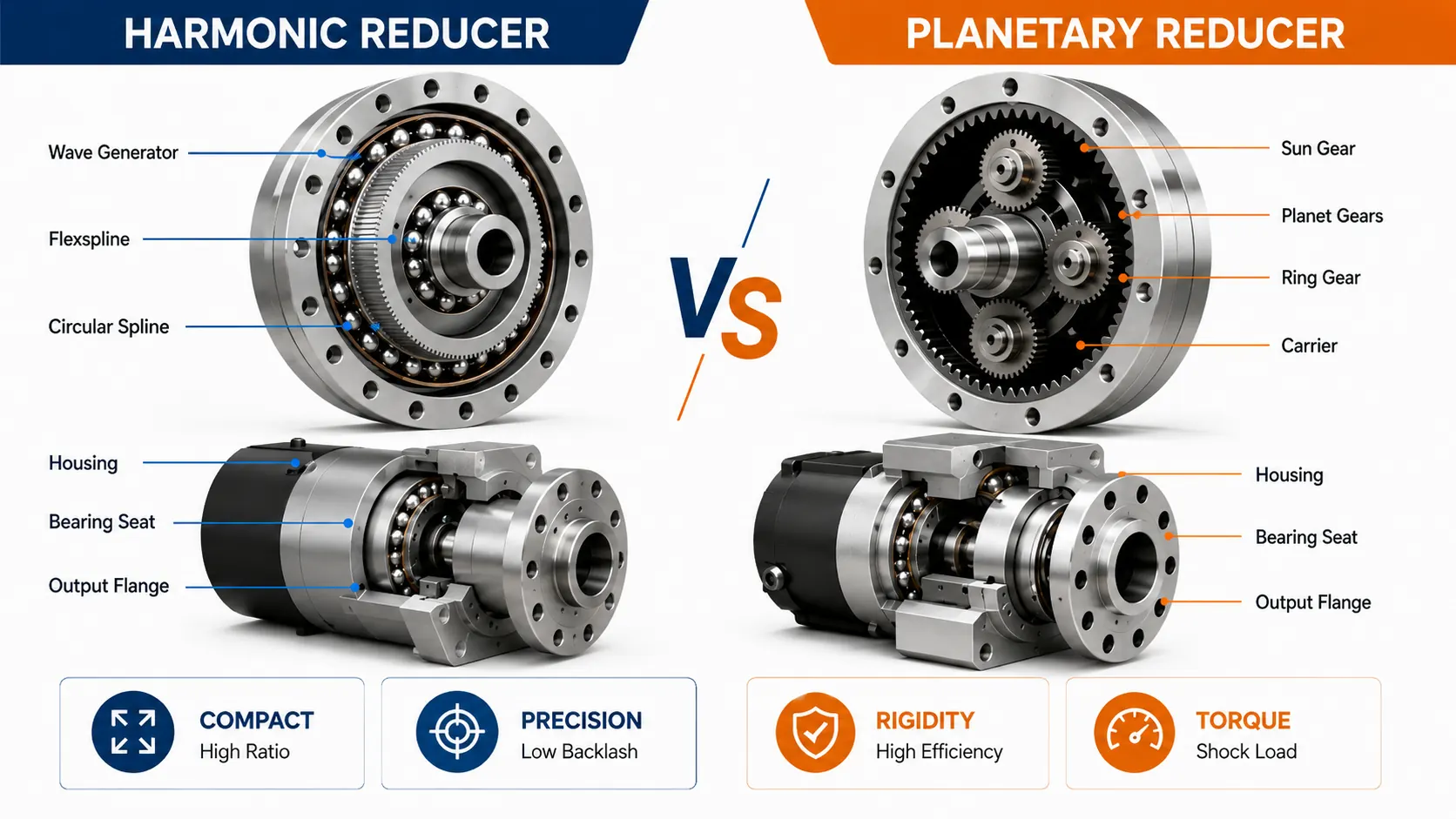
For humanoid robot joints, harmonic reducers and planetary reducers do not have a universal winner. A harmonic reducer uses controlled flexspline deformation to produce a high ratio and very low backlash in a compact envelope. A precision planetary reducer uses rigid sun, planet, ring and carrier gearing with load sharing, which is attractive when efficiency, stiffness and shock loading become dominant.
Once the reducer is integrated into a joint actuator, catalog data is only the starting point. The motor, reducer, output bearing, encoder and output flange must all be located by the same structural system. Reducer accuracy is not joint accuracy. Housing geometry, bearing fits and assembly deformation determine whether the theoretical reducer performance survives at the robot output.
| Comparison | Harmonic reducer | Precision planetary reducer | Joint-level consequence |
|---|---|---|---|
| Transmission principle | Elastic flexspline deformation with multi-tooth engagement | Rigid sun-planet-ring meshing and load sharing | Changes the load path and support strategy |
| Single-stage ratio | Typically high | Typically lower; additional stages are possible | Affects axial length, motor speed and packaging |
| Backlash | Very low backlash is a core strength | Precision units can also be very low backlash | Both need accurate mounting datums |
| Efficiency | Depends strongly on ratio, speed and flexing losses | Single-stage precision planetary units often have an advantage | Influences continuous-duty heat and battery use |
| Stiffness and shock | Peak load and flexspline fatigue need careful review | Rigid gearing and load sharing are attractive for dynamic loading | Changes bearing and housing stiffness requirements |
| Lightweight, flat packaging | Strong advantage | Also possible, with a different stiffness tradeoff | Drives wall thickness and distortion risk |
| Hollow routing | Common and mature | Hollow planetary designs also exist | Changes bearing, encoder and cable routing |
1 | Architecture: elastic deformation vs rigid load sharing
The generic mechanism behind a harmonic reducer is strain-wave gearing. A typical set contains a Wave Generator, Flexspline and Circular Spline. The wave generator deforms the thin flexspline into an elliptical shape; the small tooth-count difference between the flexspline and circular spline converts one input revolution into a very small output movement.
A planetary reducer follows a different mechanical logic. The sun gear drives multiple planet gears, the planets mesh with a ring gear, and the carrier becomes the output in a common configuration. The important feature is not elastic deformation but load sharing among multiple rigid gear meshes.
That difference matters beyond the gearbox. It determines how torque enters the housing, how the output should be supported and how much deformation the actuator can tolerate before alignment and gear loading begin to change.
2 | Ratio and backlash: harmonic strength, precision planetary progress
One major reason harmonic reducers became common in robot joints is the ability to achieve a high ratio in one compact stage while keeping backlash very low. A high single-stage ratio can reduce the need for additional gear stages and the associated packaging and accumulated backlash.
However, the statement that planetary reducers always have large backlash is no longer useful for precision servo systems. Modern precision planetary reducers can reduce backlash substantially through gear geometry, bearing support, preload and manufacturing control. Harmonic and planetary architectures should therefore be viewed as parallel precision-motion options rather than a simple high-end versus low-end hierarchy.
| Design question | Harmonic reducer tends to be attractive when | Planetary reducer tends to be attractive when |
|---|---|---|
| A large ratio is needed in one stage | Strong advantage | A multi-stage solution or different motor match may be needed |
| Very low lost motion is the priority | Core strength | Precision types can overlap the low-backlash range |
| Axial packaging is extremely tight | Often favorable | Depends on stage count and hollow architecture |
| High input speed and efficiency matter | Verify the actual efficiency and thermal curve | Often favorable |
| The joint sees repetitive shock | Peak load and life need careful checking | Rigid load sharing is often attractive |
The right question is therefore not which data-sheet number looks best. It is which reducer architecture delivers the lowest system penalty at the required torque, speed, size and life.
3 | Stiffness, shock and efficiency: why dynamic joints revisit planetary gearing
The flexspline is what makes the harmonic reducer compact and precise, and it is also a component that experiences repeated elastic deformation. Continuous speed, average torque, repeated peak torque and impact loading therefore belong in the life assessment. A joint with aggressive acceleration and deceleration cannot be sized from rated torque alone.
Planetary reducers spread load across several planet gears and use rigid tooth engagement, which makes the architecture attractive for high-dynamic duty. The architecture often balances efficiency, stiffness and shock capacity well, but actual efficiency, life and allowable shock depend on stage count, lubrication, bearing arrangement and the real duty cycle. Selection should therefore be based on the specific reducer and complete load spectrum.
At the actuator level, the difference shifts the structural priority. A harmonic joint must avoid losing reducer precision through mounting error and housing distortion. A planetary joint must also preserve alignment while keeping the bearing and housing load path sufficiently stiff under torque and impact.
4 | Lightweight and hollow designs: both are possible, with different penalties
Humanoid robots are sensitive to distal mass, so reducer diameter, axial length, hollow bore and motor integration can matter as much as the nominal ratio. The farther a joint is from the torso, the more strongly mass can influence inertia and the upstream torque requirement.
Harmonic architecture has a clear advantage in thin and compact packaging. Across the industry, development has moved toward higher torque, longer life, ultra-thin and ultra-flat layouts, larger hollow bores and lower mass. Precision planetary reducers have evolved in parallel toward lower backlash, hollow structures and higher torque density, which shows why precision motion continues to use multiple architectures.
Planetary designs can also use hollow architectures to route cables, piping and other services through the center. The better comparison is therefore not whether a hollow bore exists, but how much bearing section, housing stiffness and output support remain after the hollow passage is created.
5 | Inside a joint actuator: why the housing design starts to diverge
An integrated joint may package a frameless torque motor, reducer, bearing, encoder and brake into one module. The Housing is no longer a cover. It can simultaneously function as Motor Housing, Reducer Mount, Bearing Seat and Structural Frame.
A harmonic actuator often uses a short axial stack with thin walls, deep cavities and tightly related coaxial interfaces. Manufacturing risk therefore concentrates around residual-stress release, bearing-bore roundness, reducer-to-motor alignment and dimensional change after anodizing.
A planetary actuator also needs coaxial geometry, but high output stiffness and load path can become more prominent design constraints. When the joint carries a large overturning moment, elastic movement of the bearing seat and housing section under load may matter as much as static CMM data.
| Housing issue | Harmonic actuator | Planetary actuator |
|---|---|---|
| Primary design intent | Compact, lightweight, preserve precision mounting geometry | Stiff, stable load path, preserve gear and bearing alignment |
| Typical structural risk | Thin-wall release, clamping distortion, tilted mounting faces | Bearing-seat and housing deflection under load |
| Motor-reducer relationship | Highly integrated and sensitive to axis error | Coaxiality remains critical; input stiffness also matters |
| Output support | Isolate the precision transmission from external load where possible | Emphasize support stiffness and impact stability |
| Machining emphasis | Datum continuity, thin-wall process control, post-assembly verification | Datum continuity, bearing seats, load interfaces and stiffness |
6 | Coaxiality: critical for both, but for different reasons
A robot joint can be simplified into one rotational datum chain:
Motor Axis → Reducer Axis → Output Bearing Axis → Encoder Axis → Output Flange
In a harmonic actuator, a very low-backlash reducer can still deliver poor joint behavior if the motor bore, reducer pilot and output bearing seat do not share a stable axis. The result may be cyclic runout, bearing side load, encoder error or increased noise.
In a planetary actuator, axis error affects runout and bearing life, but it can also influence gear load distribution. If the structure tilts under load, the intended load sharing among planet gears can deteriorate.
For both architectures, this is why a drawing callout such as a small diameter tolerance does not tell the whole story. The important requirement is the geometric relationship among functional interfaces within a datum system. Machining critical bores and faces from a common setup, or through a controlled datum-transfer strategy, can be more valuable than simply tightening every isolated dimension.
7 | Bearing seats and output support: where precision meets stiffness
The reducer changes speed and torque, but radial, axial and overturning loads from the robot link must still be carried by the joint support system. Cross-roller bearings are common in compact precision joints because they can carry multiple load directions, although the actual bearing architecture depends on the actuator design.
In a harmonic actuator, the output support helps maintain precision and keeps external loads from disturbing the transmission through an unfavorable load path. In a planetary actuator, support stiffness becomes especially important under highly dynamic load.
| Bearing-seat CTQ | Why both architectures care | Harmonic-side sensitivity | Planetary-side sensitivity |
|---|---|---|---|
| Bore size and fit | Defines clearance, preload and assembly state | Press-fit distortion can reach the precision output | Fit stability under high load |
| Roundness / cylindricity | Controls bearing load distribution | Thin housings can lose roundness after unclamping | Loaded housing geometry must remain stable |
| Shoulder perpendicularity | Controls bearing attitude | Output tilt amplifies runout | Tilt changes the load path |
| Coaxiality | Connects reducer and output axis | Consumes the low-backlash accuracy budget | Influences gear, bearing and output alignment |
| Post-assembly verification | Free-state geometry is not the final state | Bearing preload and bolt torque can distort thin walls | Clamp force can shift support geometry |
8 | Output flange: both architectures end at the same interface
Whether the internal reducer is harmonic or planetary, the next robot link receives motion and torque through the Output Flange. It is therefore the final mechanical interface between transmission performance and robot kinematics.
Face runout creates axial wobble, radial runout creates eccentric motion, mounting-hole position affects the next link datum, and perpendicularity between the mounting face and the rotation axis changes joint-axis orientation. The error may be small at one joint but can propagate through a serial kinematic chain.
This is why a low reducer backlash does not automatically create high end-effector accuracy. Reducer, bearing seat, encoder and output flange must operate as one stable dimensional chain.
9 | Manufacturing CTQ comparison: which dimensions actually govern actuator performance
A joint housing drawing may contain dozens or hundreds of dimensions, but not every feature deserves equal process-control effort. The critical task during prototype and production planning is to identify the CTQs that directly affect joint function.
| Manufacturing CTQ | Harmonic actuator concern | Planetary actuator concern | Typical verification |
|---|---|---|---|
| Reducer locating bore | Prevent reducer eccentricity | Preserve input, gear train and output center | CMM / coaxiality |
| Motor stator bore | Maintain air gap and input axis | Maintain air gap and high-speed input stability | CMM / roundness |
| Output bearing bore | Prevent thin-wall distortion after assembly | Maintain geometry under high support load | Roundness, cylindricity, assembly recheck |
| Mounting face | Prevent reducer tilt | Prevent bearing and gear-axis tilt | Flatness, perpendicularity |
| Output flange | Preserve joint-axis orientation | Maintain stable high-torque output | Face runout, radial runout, position |
| Housing wall stability | Lightweight design increases distortion risk | Lightweight design must retain stiffness | Recheck after roughing and final CMM |
| Surface-treatment allowance | Fits need masking or dimensional planning | Fits and locating diameters are equally sensitive | Pre- and post-anodize checks |
| Assembly deformation | Bearing preload and bolt torque can be significant | Clamp force and load interfaces can shift geometry | Measurement in assembled condition |
The central lesson is that actuator structures are not ordinary covers. Functional datum relationships matter more than applying an unnecessarily tight tolerance to every dimension.
10 | Failure modes compared: the same noise can have a different root cause
When an actuator develops noise, heat, runout or position drift, the reducer is easy to blame first. Structural parts and assembly state can be equally important.
| Symptom | Harmonic actuator: inspect first | Planetary actuator: inspect first |
|---|---|---|
| Periodic output runout | Reducer pilot, output bearing and flange coaxiality | Input/output axes, bearing seat and flange coaxiality |
| Higher rotational resistance after assembly | Thin housing lock-up, bearing preload | Bearing preload, housing tilt, output-support distortion |
| Increased noise | Tilted mount, bearing side load, input eccentricity | Uneven gear loading, bearing side load, inadequate housing stiffness |
| Abnormal heat | Duty cycle, bearing state, mounting stress | Gear/bearing loss, input speed, preload |
| Batch-to-batch feel variation | Thin-wall drift, anodize and assembly variation | Fit, bearing state and assembly-torque variation |
The table is not a fault diagnosis by itself. Its purpose is to keep the reducer, structure and assembly inside the same verification loop.
11 | Prototype to production: both architectures converge on process capability
At ten prototypes, engineers can solve many problems by selection, rework and manual adjustment. At thousands of units, those methods stop scaling. The question changes from whether one compliant part can be made to whether the CTQ distribution remains stable over time.
Harmonic actuator housings can be sensitive to residual material stress, clamping force, tool wear and anodizing, especially around thin walls, Bearing Bores and Reducer Datums. Planetary actuator structures face many of the same issues, with additional emphasis on the consistency of stiff bearing seats and load interfaces.
Production control should therefore move the true CTQs into SPC and capability monitoring rather than treating every drawing dimension equally. Bearing Bore, Reducer Locating Bore, Motor Bore, Output Flange Runout and the main coaxial relationships are good candidates for defined measurement methods, sampling frequency, tool-life rules and reaction plans.
12 | Selection matrix: when the design tends toward harmonic or planetary
It is risky to turn joint location into a fixed rule such as shoulder equals harmonic and knee equals planetary. Different robot OEMs use different torque density, speed, gait, cost and life assumptions, so the same joint can support different reducer architectures.
A better approach is to convert the requirement into engineering weights:
| Design condition | Tends toward harmonic | Tends toward precision planetary |
|---|---|---|
| High ratio required in one stage | ◎ | △ |
| Very low backlash is primary | ◎ | ○ to ◎ |
| Axial envelope is extremely tight | ◎ | ○ |
| Low mass is primary | ◎ | ○ to ◎ |
| High-efficiency continuous duty | ○ | ◎ |
| Frequent acceleration and deceleration | ○ | ◎ |
| Shock and peak load dominate | Requires careful life verification | ◎ |
| High output stiffness | ○ to ◎ | ◎ |
| Hollow routing | ◎ | ◎ |
| Cost and supply-chain maturity | Product and platform dependent | Product and platform dependent |
The symbols are not universal rankings. Final selection should use the actual reducer data, load spectrum and life requirement.
13 | DFM and RFQ: communicate the complete joint boundary
A housing drawing alone may not reveal the functional risk of an actuator structure. The earlier the manufacturing team understands how the reducer, bearing and motor interact, the easier it is to distinguish tolerances that truly need tightening from those that can be handled through datum strategy, process planning or assembly control.
| RFQ / DFM input | Why it matters |
|---|---|
| 2D drawing + 3D model | Reveals GD&T, thin walls, deep cavities and access |
| Reducer model and mechanical interface | Defines locating bore, mounting face and load boundary |
| Motor and bearing specifications | Defines fits, coaxiality, preload and assembly path |
| Continuous / peak torque and duty | Supports housing-stiffness and interface-risk review |
| Functional datums and tolerance chain | Separates ordinary dimensions from CTQs |
| Material and condition | Influences residual stress, cutting sequence and stability |
| Anodize, plating or other finishing | Requires fit masking and dimensional allowance planning |
| Prototype, pilot and annual volume | Drives fixture, tooling, inspection and SPC strategy |
| Inspection and assembly validation | Defines CMM, roundness, runout and assembled-state acceptance |
For an actuator manufacturer developing Small, Medium and Large Joint platforms, reusing a coherent datum system, fixture logic and inspection method across the family can make production control easier than redefining every joint from zero.
14 | Conclusion: the comparison ends at the complete actuator, not the gearbox
Harmonic reducers put high single-stage ratio, very low backlash and compact packaging at the center of the architecture. Precision planetary reducers form a strong alternative through rigid load sharing, efficiency, stiffness and dynamic load capacity. Both precision reducer architectures have clear application space in compact industrial robots and humanoid robot joints.
For a humanoid actuator, both paths eventually converge on the same manufacturing question:
Motor → Reducer → Bearing → Encoder → Output Flange
Can these elements be held in a lightweight, stiff and repeatable structural system that remains stable in production?
That is why reducer selection should not stop at ratio, backlash or rated torque. The design must close the loop across error budget, load path, thermal behavior, life, housing structure, bearing support, assembly method and process capability.
FAQ
Should a humanoid robot use a harmonic reducer or a planetary reducer?
There is no single reducer type that fits every joint. High single-stage ratio, very low backlash, compact packaging, and low mass often favor a harmonic reducer, while high efficiency, stiffness, shock capacity, and highly dynamic duty often favor a precision planetary reducer. The final choice should consider continuous torque, peak torque, ratio, speed, space, weight, life, and cost together.
Does a harmonic reducer always have less backlash than a planetary reducer?
Harmonic reducers are structurally well suited to very low backlash, but precision planetary reducers can also achieve low backlash. The comparison should not rely on reducer type alone; it should use the actual model specification for backlash, torsional stiffness, life, and the complete joint error budget.
Why can a joint still have runout or noise when the reducer itself is highly accurate?
Joint accuracy is not determined by the reducer alone. Coaxiality, perpendicularity, roundness, assembly deformation, and preload across the motor bore, reducer locating bore, output bearing seat, encoder datum, and output flange all enter the final error chain. A high-accuracy reducer mounted to an unstable structural datum can still show runout, noise, heat, or reduced life.
What information should be included in an RFQ for actuator structural parts?
Provide 2D drawings and 3D models, reducer model and mounting interface, motor and bearing specifications, continuous and peak torque, functional datums and GD&T, material and heat-treatment condition, surface treatment, critical fits, prototype and production volumes, and any CMM, runout, or assembly validation requirements.
