
In This Article
Direct answer
The tables in this article are not intended to rank materials from best to worst. They are a decision tool: first classify the component, then identify its dominant load and unacceptable failure mode, and only then compare material families, manufacturing routes and cost.
Use the article in four steps:
classify the structural role
→ identify the governing load and failure consequence
→ screen material and process families
→ confirm the choice through joints, environment and life testing
A component that locates bearings, carries fall impact and removes motor heat should not be converted to polymer only because its density is lower. A sensor and harness carrier, on the other hand, may not justify a fully machined aluminum part.
A humanoid skeleton should be divided by function before materials are selected.
| Structural class | Typical locations | Primary requirement | Preferred direction |
|---|---|---|---|
| Class A: primary and safety-critical | Hip, knee and ankle load paths, thigh and shin links, bearings and reducer interfaces | Stiffness, fatigue, fall impact and preload | Steel, aluminum, titanium, continuous CFRP/CFRTP and hybrids |
| Class B: complex secondary frame | Motor, battery, sensor and joint peripheral structures | Integration, low mass and dimensional stability | Aluminum, magnesium, PA66-GF/CF, PA10T, PPS and reinforced PEEK |
| Class C: functional precision part | Gears, bushings, cages, guides and insulators | Wear, friction, heat and low moisture | PEEK, PPS, POM, PA and metal-polymer combinations |
| Class D: cover and protection | Covers, guards, lids and service panels | Impact, flame rating, appearance and repair | FR PA, PC/ABS, Mg/Al sheet or composite shells |
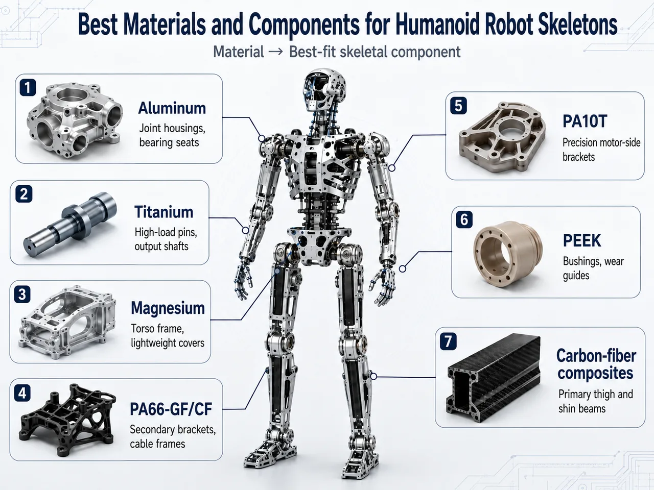
A practical leg often combines continuous carbon-fiber links, aluminum joint ends, steel or titanium shafts, PA10T sensor brackets, PEEK bushings and flame-retardant covers.
Different materials are best suited to different skeletal components in a humanoid robot. Metals fit high-load interfaces, engineering plastics fit integrated functional brackets, and carbon-fiber composites fit lightweight primary beams.
1. Why tensile strength alone is insufficient
Tensile strength is easy to find on a datasheet, but robot structures often fail first through deflection, joint relaxation, creep or fatigue. The first design question should be the unacceptable failure: positioning drift, preload loss, sudden fracture or hidden post-impact damage.
For a bearing seat, modulus and creep may matter more than ultimate tensile strength. For a long link, specific stiffness and fatigue dominate. Near a battery, flame and electrical requirements may eliminate a material before strength is considered.
| Property | Controls | Typical failure if ignored |
|---|---|---|
| Elastic modulus | Deflection, positioning and gear mesh | Strong but too flexible |
| Specific stiffness | Structural efficiency by mass | Lightweight but vibration-prone |
| Fatigue | Reversing-cycle life | Static pass, service crack |
| Creep | Bolt preload, bearings and backlash | Long-term loosening |
| Moisture | PA dimensions and stiffness | Hot-wet assembly drift |
| Impact/notch sensitivity | Falls and hole edges | Sudden fracture |
| Thermal expansion | Bearings, encoders and sensors | Temperature-dependent error |
| Anisotropy | Fiber and laminate direction | Direction-dependent strength |
| Electrical behavior | Insulation, antennas and sensors | Leakage or interference |
| Joinability | Inserts, bonds and end fittings | Joint fails before material |
2. Metals compared
Metals remain the baseline for high preload, precision interfaces and primary impact paths because bearing, thread, shaft and inspection practices are mature.
A useful decision rule is: steel for compact high load, aluminum for overall balance, magnesium for broad-area mass reduction and titanium for high load where section size is limited. The objective is not one metal throughout the robot, but the right metal at each interface.
| Material | Main advantage | Main limitation | Best fit |
|---|---|---|---|
| Steel | High modulus, fatigue and preload capability | High mass | Shafts, gears, pins, bolts and wear inserts |
| Aluminum | Balanced mass, machining, heat transfer and interfaces | Lower modulus and thin-wall distortion | Housings, bearing seats, flanges and end fittings |
| Magnesium | Very low density and useful damping | Corrosion and fatigue control | Covers, battery housings and low/medium-load frames |
| Titanium | High specific strength and corrosion resistance | High cost and difficult machining | Compact high-load shafts, pins and interfaces |
3. Polymer and composite systems compared
Polymers and carbon-fiber composites add value through low inertia, integrated functions and reduced part count, not merely lower density.
First decide whether the component needs complex three-dimensional molding or continuous load transfer along a link. Reinforced PA, PA10T, PPS and reinforced PEEK suit the first case; continuous CFRP or CFRTP suit the second.
| System | Main advantage | Main risk | Typical use |
|---|---|---|---|
| PA66-GF | Mature, insulating and cost-effective | Moisture, weld lines and creep | Harness frames and medium-load brackets |
| PA66-CF | High specific stiffness and low shrinkage | Conductivity and anisotropy | Sensor frames and low-inertia supports |
| PA10T-GF/CF | Hot-wet dimensional retention | High molding window and weld lines | Motor-side and outdoor precision frames |
| PPS-GF/CF | Low moisture and chemical stability | Brittleness and impact | Electrical and drive frames |
| Unfilled PEEK | Heat, wear and chemical resistance | Moderate stiffness and high cost | Bushings, gears and insulators |
| Reinforced PEEK | High-temperature stiffness and stability | Processing and notch sensitivity | Small high-load functional structures |
| Continuous CFRP | Tailored high specific stiffness | Delamination and hidden damage | Long primary links |
| Continuous CFRTP | High stiffness with faster forming potential | Impregnation and joining | Scalable long links and shells |
4. Two reinforced PA grades compared
These two grades are useful for initial screening, but the numbers do not prove that the CF grade should always replace the GF grade. PA66-CF40 has a clear stiffness and density advantage, while its conductivity can disqualify it from some insulated, sensor or antenna locations.
Standard coupons often have favorable fiber alignment. Real ribs, holes, gates and weld lines redistribute orientation, so mold-flow and component testing remain necessary after grade selection.
| Property | PA66-GF50 | PA66-CF40 | Engineering meaning |
|---|---|---|---|
| Tensile strength | 225 MPa | 270 MPa | CF grade is stronger in the tested direction |
| Flexural strength | 325 MPa | 390 MPa | CF grade supports stiffer brackets |
| Flexural modulus | 14.2 GPa | 26.8 GPa | Major stiffness difference |
| Notched impact | 16 kJ/m² | 15 kJ/m² | Higher stiffness does not mean higher impact toughness |
| Density | 1.55 g/cm³ | 1.32 g/cm³ | CF grade lowers inertia |
| Shrinkage | 0.2% flow, 0.7% transverse | 0.1%–0.4% | Both remain directional |
| Electrical behavior | Insulating | Surface resistivity below 10³ Ω | CF grade is normally conductive |
5. Material selection matrix
These materials are not simply low-, medium- and high-end versions of the same solution. PA66-GF favors maturity and cost, PA66-CF favors specific stiffness, PA10T favors hot-wet dimensional retention, and PEEK favors heat, wear, chemicals and low moisture.
Select according to the harshest operating condition. Hot-wet dimensional drift points toward PA10T, PPS or PEEK; thin-wall stiffness and inertia point toward CF grades; a general insulating bracket may gain little from an expensive high-temperature polymer.
| Requirement | PA66-GF | PA66-CF | PA10T | PEEK / reinforced PEEK |
|---|---|---|---|---|
| Cost | Best | Medium | Higher | Highest |
| Stiffness | Medium-high | High | Medium-high to high | Medium unfilled, very high with CF |
| Moisture sensitivity | Significant | Must still be managed | Lower | Low |
| High-temperature retention | Moderate | Moderate | Good | Excellent |
| Electrical insulation | Available | Normally conductive | Available | Available |
| Complex molding | Mature | Mature but abrasive | Higher process demand | High-temperature equipment |
| Wear performance | General | General | General to good | Excellent |
| Long primary links | Not preferred | Caution | Caution | Local use only |
6. Fiber length and architecture
Fiber length changes the structure that can be designed. Short fibers follow melt into complex geometry and integrate ribs, clips and mounting features. Continuous fibers carry load along an entire beam.
Use shape complexity and continuity of the load path as the two main decision axes. Complex does not automatically mean continuous fiber, and highly loaded does not automatically mean short-fiber molding.
| Reinforcement | Process | Shape capability | Load capability | Main weakness |
|---|---|---|---|---|
| Short fiber | Injection molding | Best for complex geometry | Secondary structures | Orientation and weld lines |
| Long fiber | Injection/compression | Medium-complex | Better impact transfer | Fiber retention and flow |
| Continuous CFRP | Layup/winding/molding | Long links and shells | Primary structures | Delamination, holes and cycle |
| Continuous CFRTP | Press forming/tape placement | Long links and shells | Primary structures with scale potential | High-temperature process and interfaces |
7. Location-by-location recommendations
This table is a first-pass screen rather than a final specification. The same named component can have a different structural role on another robot. A sensor bracket may be secondary structure, but if it establishes encoder concentricity, long-term dimensional stability becomes a CTQ.
Begin with the preferred direction as a baseline. Alternatives are then evaluated for weight or cost. An “avoid as default” entry means the solution needs stronger evidence through analysis, joint tests, fatigue and fall validation.
| Location | Preferred direction | Alternative | Avoid as default |
|---|---|---|---|
| Thigh and shin links | CFRP/CFRTP with aluminum ends | Aluminum or steel hybrid | Unvalidated short-fiber molding |
| Hip, knee and ankle ends | Aluminum, titanium or steel | Composite with metal fittings | All-polymer high-preload joint |
| Reducer and bearing housing | Aluminum with local steel | Magnesium or local reinforced polymer | Low-stiffness unfilled polymer |
| Torso frame | Aluminum, magnesium or CFRP/CFRTP hybrid | High-fiber molded modules | Single all-polymer skeleton |
| Motor and drive bracket | Aluminum, PA10T-GF, PA66-CF or PPS | CF-PEEK | Unfilled commodity PA |
| Sensor/encoder carrier | PA10T, PA66-CF, reinforced PEEK or aluminum | PPS | Unstabilized high-moisture grade |
| Gear, bushing and guide | POM, PA, PEEK or wear PEEK | PPS | Continuous CFRP |
| Cover and guard | FR PA, PC/ABS, thin Mg/Al or composite | Composite shell | Expensive CF-PEEK |
8. Why molded structures crack in cyclic motion
Cyclic cracking is rarely explained by resin strength alone. Fiber orientation, weld lines, residual molding stress, local geometry and assembly preload often interact.
Start by correlating the crack with gates, weld lines, bosses, ribs and inserts. If the load path is poor, a stiffer grade may make fracture more abrupt rather than solve the root cause.
| Cause | Component symptom | Corrective direction |
|---|---|---|
| Weld line in a high-stress zone | Linear crack near holes or windows | Move gate and redesign flow |
| Fiber direction misaligned with load | Low transverse fatigue life | Mold-flow plus anisotropic FEA |
| Sharp boss root | Crack after assembly or cycling | Larger radii and support ribs |
| Excess insert interference | Radial cracking | Control insert size, temperature and preload |
| Large thickness transition | Warpage and residual stress | Uniform and gradual walls |
| High filler or flame package reduces toughness | Brittle impact failure | Rebalance flame, stiffness and toughness |
| Moisture and temperature | Stiffness and preload drift | Hot-wet conditioning and validation |
| Static testing only | Prototype pass, service crack | S-N and component endurance testing |
9. Fall-impact failure comparison
Fall selection must consider not only damage resistance but also damage detectability. Metal deformation is often visible, molded composites may crack at holes or weld lines, and CFRP may delaminate internally with little external evidence.
Where field nondestructive inspection is unavailable, use replaceable absorbers, impact indicators, local metal guards or conservative laminate design to manage hidden damage.
| Material | Typical failure | Visual detectability | Recommended inspection |
|---|---|---|---|
| Metals | Yield, bend, dent or crack | Usually good | Dimension and crack inspection |
| Short-fiber polymer | Hole-edge, weld-line or boss fracture | Medium | Magnification, CT or section |
| CFRP | Delamination, internal crack or core crush | Often poor | Ultrasonic, thermography, tap or CT |
| Bonded hybrid | Adhesive disbond and end separation | Often poor | Interface inspection and stiffness retest |
10. Joint design comparison
A composite main member succeeds or fails at the point where load enters a metal joint. The connection must manage bearing, peel, adhesive aging, bolt preload and galvanic isolation.
Safety-critical joints should be judged by fatigue stiffness retention and aged residual strength, not only initial pull-out strength. Redundant load paths can be more valuable than the strongest single joint test.
| Joining method | Advantage | Risk | Best fit |
|---|---|---|---|
| Co-cured metal end | Continuous load transfer | Process and inspectability | Long primary links |
| Adhesive bonding | Distributed load and no cut fibers | Surface preparation and aging | CFRP-aluminum ends |
| Bolting | Serviceable | Hole bearing and delamination | Modular systems |
| Bonding plus bolts | Redundancy | Weight and process complexity | Safety-critical joints |
| Overmolding | Functional integration | Thermal mismatch and interface | Metal inserts with molded frames |
| Glass-fiber isolation layer | Galvanic isolation | Process control | Carbon fiber against aluminum |
11. Prototype-to-production validation
One prototype test cannot replace material, joint and component validation. The efficient sequence removes unsuitable materials with inexpensive coupons before adding geometry, environment and realistic loads.
Each stage needs a release criterion. A system should not proceed to fall testing before joint fatigue is understood, and dry strength is irrelevant when hot-wet dimensions already fail.
| Stage | Main work | Release criterion |
|---|---|---|
| Material screening | Coupon, hot-wet and baseline fatigue | Candidate list |
| Structural analysis | Anisotropic FEA, mold flow or laminate analysis | Load path and risk zones |
| Joint test | Bolts, inserts, adhesive and end fittings | Static and fatigue joint data |
| Prototype | Stiffness, strength, modal and assembly | CTQ baseline |
| Endurance | Reversing bending, torsion and vibration | Target cycle count |
| Environment | Hot-wet, thermal cycling and chemicals | Property retention |
| Fall test | Multi-direction impact | No unsafe failure |
| Pilot | Warpage, mass, defects and cycle | Process capability |
| Production | Frozen parameters and traceability | Stable CPK and life audit |
12. Final decision matrix
Use this matrix by identifying the one or two governing requirements rather than attempting to optimize every property simultaneously.
When requirements conflict, preserve safety, stiffness and life first, then optimize mass and cost. Bearing interfaces prioritize modulus and preload retention; long links prioritize specific stiffness; electrical brackets prioritize insulation and flame behavior.
| Requirement | Preferred material direction |
|---|---|
| Precision bearing and reducer interface | Aluminum, steel or titanium |
| Long high-specific-stiffness member | Continuous CFRP or CFRTP |
| Complex integrated molding | PA66-GF, PA10T or PPS |
| High-stiffness molded bracket | PA66-CF, PA10T-CF or CF-PEEK |
| Hot-wet dimensional stability | PA10T, PPS or PEEK |
| High-temperature wear | PEEK or wear-modified grade |
| Electrical insulation | Unfilled or GF insulating grade |
| Conductivity or static dissipation | Dedicated CF or conductive grade |
| Primary fall-impact path | Metal or fully validated hybrid |
| Large low-load cover | Magnesium, FR polymer or composite shell |
13. RFQ information
Material selection is only as good as the RFQ. A drawing without a load spectrum, cycle count, fall case and environment forces suppliers to quote from static experience rather than determine whether polymers or composites are appropriate.
A strong RFQ states the function, failure consequence and validation target. This allows early decisions about machining, molding, casting, composite processing, inserts, NDT and endurance cost.
| Input | Engineering use |
|---|---|
| Robot mass and reduction target | Lightweighting benefit |
| 2D and 3D data | Load paths, holes and interfaces |
| Joint torque and load spectrum | Stiffness and fatigue class |
| Fall cases | Impact and fail-safe design |
| Temperature, humidity and fluids | Moisture, creep and compatibility |
| Flame and electrical requirements | Grade selection |
| Bearings, bolts, inserts and interference | Interface design |
| Target life and cycle count | Endurance plan |
| Allowed deflection and modes | Stiffness target |
| Volume and cycle | CNC, molding, casting or composite process |
| Inspection requirement | CMM, CT and NDT planning |
| Service strategy | Modular and removable joints |
Frequently asked questions
Can PA66-CF directly replace an aluminum humanoid robot skeleton?
Not by comparing material strength alone. PA66-CF offers attractive specific stiffness, low density and low shrinkage for complex secondary frames, sensor brackets and low-inertia structures, but performance depends on fiber orientation, weld lines, hole-edge stress, temperature, moisture and creep, and carbon-fiber compounds are normally conductive. Bearing seats, reducer interfaces, primary fall-impact paths and highly preloaded joints should remain metallic or use fully validated hybrid structures.
What is the main advantage of PA10T over conventional PA66?
PA10T is a semi-aromatic high-temperature polyamide that normally has lower moisture sensitivity, better dimensional retention in hot and humid conditions, improved hydrolysis resistance and better high-temperature performance than conventional PA66. It is useful around motors, precise sensor frames and dimension-critical supports, but it remains an anisotropic fiber-reinforced molding material whose weld lines, molding window and stress concentrations must be controlled.
Is PEEK always more suitable than glass- or carbon-fiber-reinforced PA for robot skeletons?
No. Unfilled PEEK offers excellent heat, chemical, hydrolysis and wear resistance and useful toughness, but its room-temperature stiffness can be lower than highly glass- or carbon-fiber-reinforced PA. Reinforced PEEK greatly increases stiffness and dimensional stability but also raises material cost, processing temperature, tooling requirements and notch sensitivity. PEEK is best reserved for high-temperature, wear, chemical and precision functional locations rather than the entire skeleton.
Where are continuous CFRP and CFRTP most suitable in a humanoid robot?
Continuous CFRP and CFRTP are most suitable for long primary members such as thigh, shin, arm and torso links because fibers can be aligned with the load path to achieve high specific stiffness. Joint ends, bearings, bolts and reducer connections normally require metallic end fittings and local reinforcement. Hole bearing, delamination, hidden impact damage, layup, metal joining, galvanic isolation and production inspection must all be validated.
