
In This Article
Direct Answer
The most important Rubin-era change is not simply that another generation of AI servers uses liquid cooling. It is that the boundary of liquid cooling is expanding.
In many earlier direct-to-chip systems, liquid primarily removed heat from the GPU and CPU, while memory, power electronics, storage, NICs, switch devices and other distributed heat sources still depended partly on airflow.
At several hundred kilowatts per rack, that hybrid model runs into a simple problem:
A high percentage of heat capture does not necessarily mean a small residual heat load.
At NVIDIA GTC 2026, CoolIT used a 500kW rack to illustrate the issue: even at 90% heat capture, roughly 50kW remains for air cooling. NVIDIA’s public description of Rubin goes further, stating that the generation is designed for 100% liquid cooling, with chips and networking components cooled by liquid and no server fans required.
The manufacturing chain therefore becomes:
GPU / CPU → Memory / Power → NIC / Switch / Storage → more liquid-cooled interfaces → more manifold branches → more QD and tubing interfaces → a more complex flow and pressure-drop network → tighter leak, cleanliness, corrosion and reliability control.
That is the part of Rubin that matters most to precision manufacturing.
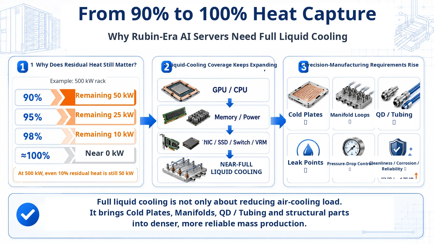
1. Why 90% Heat Capture Is Still a Large Problem at 500kW
Heat capture is easy to misread when only the percentage is considered.
For a 500kW IT load:
| Liquid Heat Capture | Heat Removed by Liquid | Theoretical Residual Heat Requiring Other Cooling |
|---|---|---|
| 90% | 450 kW | 50 kW |
| 95% | 475 kW | 25 kW |
| 98% | 490 kW | 10 kW |
| 99% | 495 kW | 5 kW |
| 100% | 500 kW | Ideal boundary near 0 kW |
The important number is the absolute residual air load.
Fifty kilowatts is already comparable to the entire heat load of a dense conventional rack. If future AI racks move toward 1MW or beyond, leaving the same 10% to air would create an even larger residual cooling problem.
CoolIT’s GTC 2026 presentation argued that moving toward 98–99% heat capture becomes increasingly important as rack power rises, because reducing the remaining air load is what allows the facility to shrink or eliminate auxiliary air-cooling infrastructure.
NVIDIA GTC 2026: Liquid Cooling — How to Achieve 100% Heat Capture on 500kW+ Racks
2. Rubin Expands Liquid Cooling Beyond the GPU and CPU
Many liquid-cooled servers have historically been hybrid systems.
GPUs and CPUs use cold plates, while the server still contains fans and heat sinks to cool DIMMs, VRMs, SSDs, NICs, switch components and other lower-power but distributed heat sources.
That architecture can work when the rack power is lower, because the air system only handles the remainder. At several hundred kilowatts per rack, however, even a small residual percentage represents a substantial thermal system.
NVIDIA’s 2026 Rubin cooling description changes this boundary:
- Rubin is described as NVIDIA’s first AI infrastructure generation to achieve 100% liquid cooling;
- chips and networking components move into the liquid-cooling path;
- server fans are eliminated;
- coolant inlet temperature can reach about 45°C;
- in suitable climates and facility designs, dry coolers can reduce the need for mechanical chillers and evaporative cooling.
The shift is therefore not only higher GPU power. It is the transfer of heat sources that previously belonged to the air domain into the liquid domain.
NVIDIA: Hotter Than a Hot Tub — The 45°C Breakthrough to Cool AI’s Biggest Machines
3. What Additional Components Enter the Liquid-Cooling Path?
CoolIT’s GTC 2026 presentation described heat-capture coverage in three practical levels.
| Heat-Capture Stage | Main Liquid-Cooled Components | Cooling-Structure Change |
|---|---|---|
| About 70% | High-TDP GPU and CPU devices | A small number of high-performance cold plates remove most heat |
| About 85% | Adds DIMMs and power-supply heat | Cooling expands to more distributed heat sources |
| Near 100% | Adds HBM, VRMs, SSDs, NICs and other peripheral or pluggable devices | More local cooling interfaces, combined plates and branches |
| Rubin full-liquid target | Compute and networking components move into the liquid system | Server architecture moves from hybrid cooling to a liquid-dominated thermal path |
A manufacturing team should not interpret this as one cold plate for every device.
High-heat-flux GPUs and CPUs may still use dedicated high-performance plates, while memory, VRMs, SSDs, NICs or switch components can be covered by multi-component plates, monolithic cooling structures, localized coolers or other liquid interfaces.
The real increase is in:
the number of heat sources that must be reliably connected to the liquid thermal path.
4. More Cold Plates Are Only the First Layer; the Flow Network Is the Real Change
From a part-level view, 100% liquid cooling can look like a simple increase in cold-plate volume.
The more important change is the fluid network:
GPU/CPU cold plates
↓
more Memory / VRM / NIC / Switch cooling interfaces
↓
more internal server branches
↓
more server-manifold ports
↓
higher rack-manifold flow
↓
more QDs, hoses, tubes and interfaces
↓
higher CDU and TCS capacity
A GTC 2026 session on liquid-cooling readiness for Vera Rubin also emphasized that generation changes do not necessarily require a completely new facility cooling architecture. A more extensible approach keeps the TCS manifold, CDU methodology and rack-drop concept stable while scaling CDU count, endpoints and rack interfaces for higher flow.
That creates two supply-chain trends:
| Trend | Manufacturing Meaning |
|---|---|
| Denser cooling inside the server | Smaller, more integrated cold plates, valve blocks, manifolds and connector seats |
| More standardized rack and facility interfaces | Manifold interfaces, mounting structures and tubing supports can become repeatable production part numbers |
For precision manufacturers, the second trend is especially important. The attractive opportunity is not dozens of one-off prototype drawings every generation, but a set of stable mechanical interfaces that repeat across production.
5. Which Precision-Machined Parts Grow With Full Liquid Cooling?
As liquid coverage expands from the GPU and CPU to the entire rack, machining opportunities extend beyond the cold plate.
| Component | Typical Manufacturing Scope | Key CTQs |
|---|---|---|
| GPU/CPU high-performance cold plate | Base, channels, cover, ports | Contact surface, channel geometry, flatness, pressure drop, sealing |
| Memory / VRM / NIC cooling structure | Multi-zone or monolithic plate, local passages | Thin wall, position, local flatness, flow distribution |
| Server manifold | Multi-branch deep holes, cross holes, valve ports | Bore position, diameter, burrs, cleanliness, branch resistance |
| Rack manifold | Long flow paths, multiple ports, mounting structure | Total flow, port position, branch consistency, proof pressure |
| Valve/distribution block | Internal passages, valve and sensor ports | Coaxiality, sealing faces, bore quality, cleanliness |
| QD mounting seat / interface block | QD alignment, mounting plate, tubing transition | Mating position, stiffness, insertion direction, seal interface |
| Tubing and cooling-module brackets | Support, anti-vibration, keying | Dimensional chain, service space, vibration, accessibility |
The QD itself is usually supplied by a specialist connector manufacturer, but its mounting seat, manifold port, support structure and mating dimensional chain become part of the precision-machining and assembly problem.
Full liquid cooling therefore creates opportunity not because every component must be machined in-house, but because more functional parts must be built around standardized liquid interfaces.
6. More Branches Make Pressure Drop a Manufacturing CTQ
Even a conventional GPU/CPU cold-plate loop must balance thermal resistance and hydraulic resistance.
When memory, VRMs, NICs, switches and peripherals join the loop, the system becomes a more complex parallel network.
A slightly undersized bore, an unremoved burr, a high-loss turn or a port with reduced effective diameter can change branch flow distribution.
| Manufacturing Deviation | Possible Fluid Effect |
|---|---|
| Channel width or depth below target | Higher local pressure drop |
| Burrs left in deep holes | Reduced effective area and released particles |
| Misaligned cross holes | Added local resistance and turbulence |
| Large steps at port transitions | Additional local pressure loss |
| Branch-bore variation | Uneven flow in parallel circuits |
| Joining distortion | Changed channel section and port location |
A mature drawing therefore cannot stop at dimensional conformity.
For manifolds and cold plates, dimensional tolerance must ultimately be connected to flow and pressure-drop performance.
Production control should link critical bore sizes, channel sections and port geometry to functional flow testing rather than relying only on final external dimensions.
7. More Interfaces Mean Leak Control Cannot Be Left to One Final Test
Full liquid cooling creates more:
- cold-plate ports;
- branch tubing;
- manifold connections;
- quick-disconnect interfaces;
- valve and sensor ports;
- seal grooves and joined areas.
A larger number of interfaces does not mean leak probability rises in a simple linear way, but it does increase the number of potential failure locations that must be controlled.
| Potential Leak Location | Common Cause | Manufacturing and Validation Focus |
|---|---|---|
| Cold-plate cover joint | Incomplete joining, distortion, contamination | Joining window, leak test, proof pressure |
| O-ring groove | Incorrect geometry, roughness or compression | Groove width, depth and surface condition |
| Manifold thread/port | Position error or damaged sealing face | Coaxiality, face condition, thread and cleanliness |
| QD mounting position | Mating offset or insufficient bracket stiffness | 3D position, insertion dimensional chain |
| Weld/braze area | Heat input, gap or material issue | Pre-cleaning, tooling, post-join leak validation |
| Sensor interface | Small-thread or sealing-face damage | Machining integrity, assembly torque and leak test |
For a dense liquid-cooling assembly, a more robust sequence is:
control sealing features at part level → leak-test subassemblies → proof and leak-test the assembly → validate flow and pressure drop → repeat leak validation after environmental tests when required.
Leak control becomes an in-process discipline rather than a single end-of-line activity.
8. Cleanliness Becomes Harder as Liquid Coverage Approaches 100%
More liquid branches mean more internal passages, valve ports, QDs and small cooling features.
That makes a small particle a system-level reliability risk.
Typical contamination sources include:
- CNC chips and burrs;
- residue from deep-hole drilling;
- cleaning-fluid residue;
- joining or surface-treatment residue;
- seals and assembly operations;
- tube cutting and installation;
- secondary contamination during storage and shipping.
A particle that does not completely block a main GPU cold plate can still create a large hydraulic effect inside a smaller memory cooler, valve, QD or low-flow branch.
The real requirement is therefore not simply to “clean the part,” but to make:
deburring, washing, rinsing, drying, sealing, packaging and clean assembly one continuous cleanliness-control chain.
9. 45°C Coolant Helps the Facility, but Materials Still Need a Defined Compatibility Window
NVIDIA describes Rubin systems as accepting coolant at about 45°C and returning it at a higher temperature after absorbing the IT heat load.
That higher-temperature loop can be valuable at the facility level because it brings the liquid temperature closer to outdoor ambient conditions, making dry-cooler heat rejection practical in more locations and reducing dependence on mechanical refrigeration.
For manufacturing, however, 45°C is not automatically an easier condition.
Materials, seals and coolant chemistry still have to be validated across the full operating temperature range.
NVIDIA has publicly described a 75% water / 25% propylene-glycol coolant for Rubin, but that should not be copied as a universal specification for every liquid-cooling project. Customers may use different water quality, inhibitor packages, seal materials and wetted-metal combinations.
A manufacturing review should therefore confirm:
| Item | Why It Matters |
|---|---|
| Wetted metals | Aluminum, copper and stainless combinations affect corrosion design |
| Coolant chemistry | Drives material compatibility, inhibitors and seal selection |
| Surface treatment | Must be reviewed for wetted surfaces and corrosion behavior |
| Seal material | Must match fluid, temperature and service life |
| Cleaning residue | Can alter coolant chemistry and contamination level |
| Dissimilar-metal joints | Require galvanic-corrosion and isolation review |
CoolIT’s GTC 2026 presentation also discussed wetted aluminum and emphasized that reliable mixed-metal systems depend on appropriate coolant chemistry and long-term validation.
The right question is not simply “Can aluminum be wetted?” or “Is copper always safer?”
It is whether the complete combination of:
material + coolant + temperature + surface condition + service life
has been qualified.
10. CTQs Must Expand From a Single Part to the System
Traditional cold-plate prototypes often focus on:
- flatness;
- channel geometry;
- leak test;
- proof pressure;
- appearance.
A full-liquid system requires a broader CTQ structure.
| CTQ Level | Typical Controls | Purpose |
|---|---|---|
| Part geometry | Flatness, bore size, position, seal groove, ports | Ensure geometry and assembly |
| Internal quality | Burrs, particles, residual fluid, joined condition | Protect flow-path integrity and cleanliness |
| Functional performance | Leak, proof pressure, flow, pressure drop, branch balance | Validate the fluid circuit |
| System reliability | Thermal cycling, vibration, insertion cycles, corrosion, life | Validate long-term operation |
Production then adds:
- dedicated fixtures;
- tool-life management;
- SPC for critical bores and seal dimensions;
- leak-tester calibration;
- wash and rinse-fluid monitoring;
- lot traceability;
- change control.
When one rack contains many liquid-cooling parts, the cost of an occasionally unstable process is multiplied by the component count.
The manufacturing requirement that full liquid cooling really amplifies is therefore consistency.
11. Where Is the Real Opportunity for Precision Manufacturers?
Rubin matters to manufacturing not because it is an NVIDIA product, but because it represents an architectural direction.
The previous model:
liquid-cool the main heat sources + air-cool the rest
is moving toward:
compute + memory + power + storage + networking → a much larger share of heat enters the liquid path
That creates three long-term changes.
First, cooling hardware becomes a part family
The supply chain moves beyond a GPU cold plate to cooling structures with different power levels, footprints and interfaces.
Second, manifolds and interfaces become more valuable
As liquid coverage grows, stable distribution becomes more important. Server manifolds, rack manifolds, valve blocks, connector seats and mounting structures become central parts of the cooling BOM.
Third, repeatability becomes more important than one-off precision
High-density AI infrastructure does not only need one impressive prototype.
It needs:
the same part number to repeat with stable channel geometry, sealing, cleanliness, pressure drop and leak performance.
That is the capability precision suppliers should build for the Rubin era.
12. What Should Be Confirmed at RFQ Stage?
A high-heat-capture or full-liquid-cooling RFQ should not consist of only one part drawing.
| Input Category | Information to Confirm |
|---|---|
| System boundary | Target heat capture, rack power, server count, liquid-cooled components |
| Fluid conditions | Coolant, inlet temperature, target branch flow, allowable pressure drop, total flow |
| Pressure conditions | Operating pressure, transients, proof and burst boundary |
| Interfaces | QD type, tube size, thread, flange, port direction, assembly space |
| Materials | Wetted materials, mixed-metal interfaces, surface treatment, seal materials |
| Cleanliness | Particle limits, wash, dry, sealing and packaging requirements |
| Thermal interface | Flatness, roughness, mounting load, TIM condition |
| Reliability | Leak rate, thermal cycling, vibration, insertion life |
| Production | Prototype quantity, annual volume, CTQs, inspection rate, traceability |
Only after these boundaries are defined can a supplier decide whether a part should use CNC-machined channels, brazing, friction stir welding, mechanical sealing or another manufacturing route, and which features require 100% inspection.
Frequently Asked Questions
Does 100% Heat Capture mean absolutely no heat reaches the air?
In engineering use, 100% Heat Capture is better treated as a system target to remove essentially all IT heat through the liquid loop rather than as a claim of mathematically zero stray heat. NVIDIA describes Rubin as cooling every chip and networking component with liquid and eliminating server fans, while an actual project still needs a defined rack, server and facility heat-capture boundary and test method.
Why is 90% heat capture still insufficient for a 500kW rack?
Because 10% of 500kW is still 50kW. Even after most heat is removed by liquid, the remaining 50kW still requires a continuous air-cooling path. As rack power rises, the same residual percentage becomes a larger absolute heat load, which pushes designs toward 95%, 98%, 99% and ultimately near-100% liquid heat capture.
Does full liquid cooling require one cold plate for every component?
Not necessarily. High-heat-flux GPUs and CPUs often need dedicated high-performance cold plates, while memory, VRMs, SSDs, NICs, switch chips or pluggable components can use multi-component plates, monolithic cooling structures, localized coolers or other liquid-cooled interfaces. The key change is broader liquid coverage, not a one-to-one cold plate count.
Why do manifolds and pressure-drop control become more important at 100% liquid cooling?
As the liquid loop expands from a few GPU and CPU cold plates to many more components, the number of branches, interfaces and parallel flow paths increases. Total flow, local resistance and branch pressure drop must be balanced to avoid underfeeding high-heat components, overfeeding low-resistance branches or increasing pump power, so manifold passages, bores, turns, valve blocks and ports require system-level pressure-drop review.
What are the most direct precision-manufacturing requirements created by full liquid cooling?
Cold plates, server and rack manifolds, valve blocks, quick-disconnect mounting seats and structural interfaces become more numerous and more densely integrated. Critical requirements include thermal-contact surfaces, flow-channel dimensions, seal grooves, port position, deburring, internal cleanliness, leak and pressure testing, flow and pressure-drop validation, and material compatibility. Production also needs defined CTQs, dedicated fixtures, traceability and stable cleaning and leak-test processes.
What information should be provided when requesting a quote for 100% liquid-cooling parts?
Provide the system connection diagram, 2D drawings, 3D models, coolant and wetted materials, target flow and allowable pressure drop for each branch, operating and proof pressure, leak-rate requirement, cleanliness, thermal-contact surface requirements, quick-disconnect and tubing interfaces, surface treatment, prototype quantity, expected annual volume, and validation requirements for leak, flow, thermal performance and reliability.
