
In This Article
Direct Answer
Data center liquid cooling is not a single cold plate and it is not simply a water pipe connected to a server. It is a complete heat-transfer chain extending from the chip, through the server and rack coolant loops, to the facility heat-rejection system.
In a typical direct-to-chip architecture, heat from CPUs and GPUs passes through a thermal interface material into a liquid cold plate. Coolant then carries the heat through server manifolds, rack manifolds and piping to a coolant distribution unit, or CDU. A heat exchanger in the CDU transfers the heat into the facility-side loop for final rejection through dry coolers, cooling towers, chillers or other systems.
The path can be summarized as:
CPU / GPU → Thermal Interface Material → Cold Plate → Server Manifold → Rack Manifold → CDU → Facility Cooling
Every interface can affect temperature, flow, pressure drop, leak risk and long-term reliability. A liquid cooling project must therefore evaluate more than cold plate thermal performance.
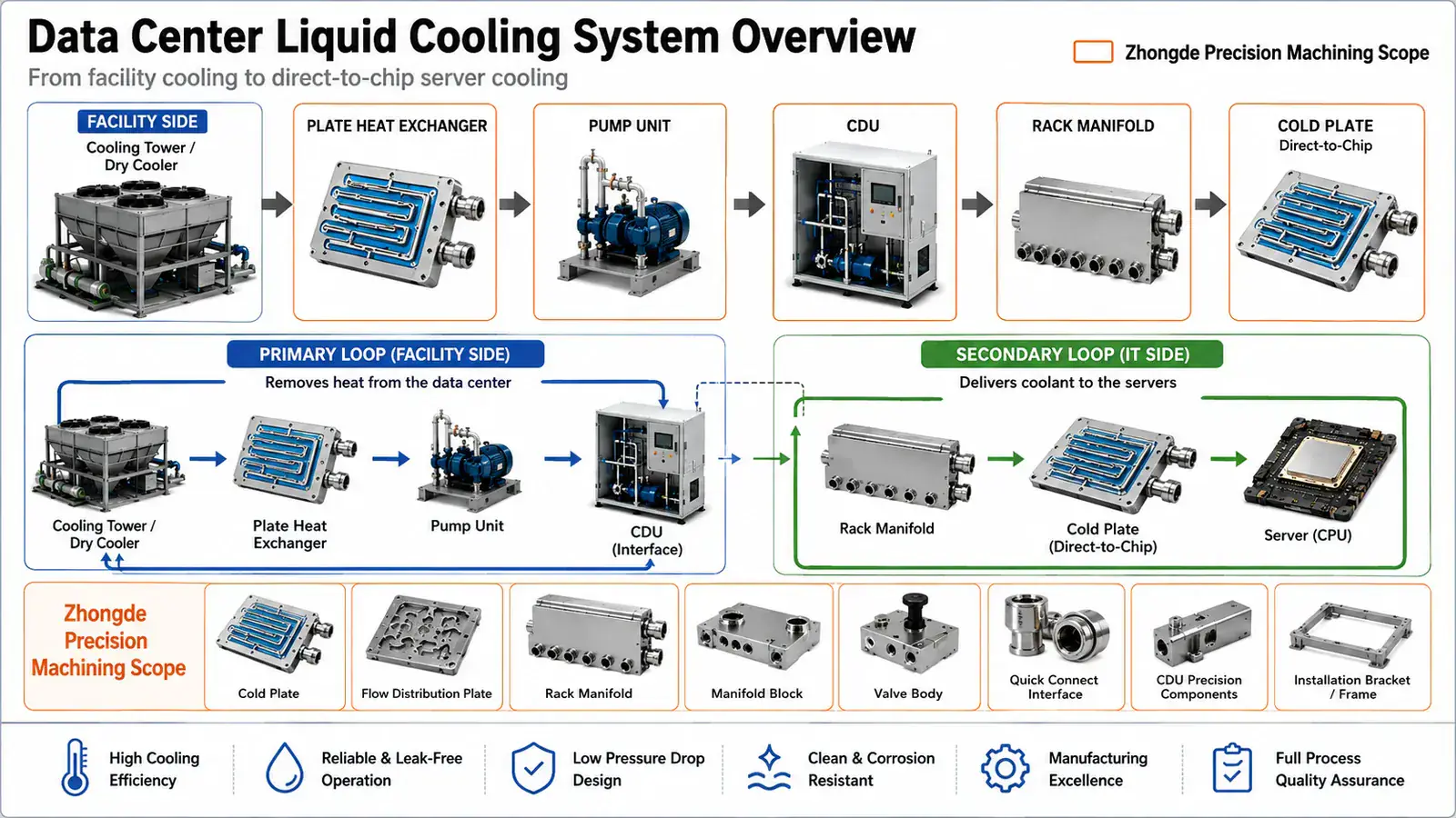
Heat-transfer path in a data center liquid cooling system and the liquid cooling components within Zhongde Precision’s manufacturing scope.
1. Why Data Centers Are Adopting Liquid Cooling
AI training, inference and high-performance computing continue to increase both processor power and rack power density. As heat becomes more concentrated, moving it away from the chip with air alone becomes increasingly difficult.
Air cooling still has an important role. It can cool lower-power devices and may continue to serve memory, networking, storage, power components and other loads. The main change is that high-power CPUs and GPUs are increasingly cooled directly by liquid.
NVIDIA documentation for liquid-cooled rack systems describes coolant flowing through rack manifolds and cold plates attached to CPUs and GPUs, while some networking and storage components remain air cooled. In practice, many systems are therefore hybrid architectures rather than fully liquid-cooled systems.
Liquid cooling is generally introduced to address several needs.
| Requirement | Contribution of Liquid Cooling |
|---|---|
| Higher chip power density | Removes heat close to the heat source |
| Higher rack power | Reduces dependence on very high airflow |
| Tighter chip temperature limits | Shortens the heat-transfer path |
| Limited floor space | Supports denser server deployment |
| Energy-efficiency targets | Can reduce part of the fan and mechanical cooling load |
| Operational control | Enables centralized flow, temperature and pressure monitoring |
Liquid cooling does not automatically guarantee efficiency. Poor matching between cold plates, manifolds, CDUs and facility systems can still create excessive pressure drop, insufficient flow or higher pumping power.
2. The Complete Heat Path from Chip to Facility
A liquid cooling system can be understood by following the movement of heat.
| Level | Main Components | Function |
|---|---|---|
| Chip level | CPUs, GPUs, accelerators | Generate heat |
| Thermal interface | TIM and mounting hardware | Transfer heat into the cold plate |
| Server level | Cold plates, hoses, server manifolds | Absorb heat and create server-side connections |
| Rack level | Rack manifolds, quick disconnects, branches | Distribute coolant to servers |
| Distribution level | CDU | Circulate, regulate and exchange heat |
| Facility level | Facility piping, pumps and heat rejection | Remove heat from the data center |
Open Compute Project documents treat cold plates, rack manifolds and CDUs as interconnected parts of the same cooling system. A rack manifold must support rack-level load while providing suitable flow distribution to multiple server branches.
From a manufacturing perspective, the heat path is also an interface chain. A dimensional, sealing, orientation or cleanliness problem at one interface can affect the entire system downstream.
3. Technology-Side and Facility-Side Loops
A typical liquid cooling system separates two coolant loops.
Technology-Side Loop
The technology-side loop, also called the secondary loop, circulates through:
- Liquid cold plates;
- Internal server tubing;
- Server manifolds;
- Quick disconnects;
- Rack manifolds;
- The secondary side of the CDU.
This loop directly contacts precision flow channels, valves, seals and server components. Coolant cleanliness, material compatibility, particle control and corrosion risk are therefore important.
Facility-Side Loop
The facility-side loop may include:
- The primary side of the CDU heat exchanger;
- Facility supply and return piping;
- Pumps;
- Dry coolers;
- Cooling towers;
- Chillers or other heat-rejection equipment.
The CDU heat exchanger separates the two loops, allowing the technology-side coolant to remain controlled instead of sending facility water directly through server cold plates.
Temperature, flow, pressure, heat-exchanger capacity and controls must be coordinated across both loops.
4. CPU and GPU Liquid Cold Plates
A liquid cold plate mounts directly on a CPU, GPU or another high-power component. It is the functional component closest to the heat source in a direct-to-chip system.
A cold plate commonly includes:
- A thermal contact base;
- Internal flow channels or heat-transfer structures;
- A cover or sealing layer;
- Inlet and outlet ports;
- Mounting and locating features;
- Sealing or joining regions.
It must maintain thermal contact, distribute coolant through the main heat-load area and remain leak-tight under pressure, temperature cycling and mounting loads.
The OCP liquid cooling cold plate requirements consider thermal performance, pressure drop, leakage, proof pressure, materials, reliability and interfaces together. A liquid cold plate should therefore not be managed as an ordinary machined part.
Typical manufacturing CTQs include:
| CTQ | Main Impact |
|---|---|
| Thermal contact flatness | Contact resistance and mounting load |
| Contact surface roughness | TIM contact condition |
| Channel width and depth | Flow and pressure drop |
| Cover or joint surface | Sealing integrity |
| Port location and geometry | Tubing installation and sealing |
| Internal cleanliness | Reliability of small channels, valves and filters |
| Leak and proof-pressure performance | System safety and life |
5. Server and Rack Manifolds
Manifolds distribute coolant. They can be divided into server-level and rack-level manifolds.
Server Manifolds
A server manifold divides supply and return connections among multiple CPU, GPU or accelerator cold plates. It must account for:
- Branch count;
- Flow balance;
- Port orientation;
- Installation space;
- Tube interference;
- Venting and draining;
- Leak-test access.
Rack Manifolds
A rack manifold runs through the rack and distributes coolant from the CDU to multiple compute trays or server nodes.
The OCP rack manifold requirements emphasize rack-level cooling capacity and suitable flow distribution to individual server loops.
Manifold manufacturing involves more than external dimensions and hole locations. Internal cross-holes, blind-hole plugs, connector seats, valve blocks, joined sections and cleaning dead zones all require attention.
| Manifold Risk | Potential Result |
|---|---|
| Large branch-resistance differences | Uneven server flow |
| Port position error | Tube interference or assembly load |
| Burrs and chips | Blocked cold plates, valves or filters |
| Unreliable cross-hole sealing | Internal or external leakage |
| Incompatible materials | Corrosion or long-term contamination |
6. Quick Disconnects, Tubing and Mechanical Interfaces
Quick disconnects allow servers to be serviced with limited coolant loss. Tubing and fittings may appear to be standard components, but they transmit dimensional error and assembly load into cold plates and manifolds.
Important interfaces include:
- Fitting threads and sealing surfaces;
- Connection direction and service clearance;
- Minimum tube bend radius;
- Fitting-to-manifold alignment;
- Support-bracket positions;
- Supply-and-return error prevention;
- Residual-fluid control after disconnection.
When a connector seat is out of position or orientation, installers may force the tube to compensate. The assembly may connect initially, but long-term stress can reduce sealing reliability.
The dimensional chain should therefore be reviewed from the cold plate and manifold through the supports and rack connection.
7. Coolant Distribution Units
A CDU is the key interface between the technology-side coolant loop and facility cooling.
A typical CDU may contain:
- A heat exchanger;
- Circulation pumps;
- Filters;
- An expansion or reservoir function;
- Temperature sensors;
- Pressure sensors;
- Flow monitoring;
- Filling and venting connections;
- Controls;
- Leak alarms.
The OCP liquid-to-liquid CDU test methodology evaluates cooling performance, flow, pressure drop, controls and test boundaries. CDU selection must consider more than total heat load; rack count, branch resistance, supply-return temperature difference and redundancy strategy also matter.
A CDU generally performs five functions:
- Circulates technology-side coolant;
- Transfers heat to the facility side;
- Controls coolant temperature, pressure and flow;
- Filters and manages the technology-side fluid;
- Detects abnormal conditions and communicates with controls.
A CDU cannot correct every downstream problem. Increasing pump pressure cannot fully compensate for blocked channels, unbalanced manifolds or excessive branch resistance.
8. Direct-to-Chip, Rear-Door and Immersion Cooling
Data center liquid cooling includes several architectures.
| Architecture | Cooling Location | Main Liquid Components | Server Impact |
|---|---|---|---|
| Direct-to-chip | CPUs, GPUs and primary heat sources | Cold plates, manifolds, CDU and QDs | Retains much of the conventional server format |
| Rear-door heat exchanger | Rack exhaust side | Rear-door coil, piping and CDU | Changes the rack and facility interface |
| Single-phase immersion | Entire server immersed in dielectric fluid | Tank, pumps and heat exchanger | Major change to server and service procedures |
| Two-phase immersion | Coolant changes phase at heat sources | Sealed tank and condensing structure | Stronger fluid, sealing and service constraints |
Direct-to-chip and immersion cooling are not simply old and new alternatives. Selection depends on power density, existing facility conditions, server design, maintenance, coolant, supply chain and total cost.
For precision manufacturing, direct-to-chip systems create demand for:
- Cold plates;
- Flow-channel plates;
- Manifolds;
- Valve blocks;
- Connector seats;
- CDU housings and structural components;
- Mounting and support components.
9. Critical Manufacturing Interfaces
Liquid cooling failures often occur between components rather than inside a single part.
| Interface | Critical Requirements | Typical Risk |
|---|---|---|
| Chip to cold plate | Flatness, roughness and mounting load | High contact resistance or uneven chip load |
| Cold plate to fitting | Threads, sealing surface and orientation | Leakage or tube interference |
| Cold plate to server manifold | Tube length, position and pressure drop | Uneven branch flow |
| Server to rack manifold | QD position and service clearance | Assembly or maintenance difficulty |
| Rack manifold to CDU | Tube size, flow and supply-return direction | Excessive pressure drop or wrong connection |
| CDU to facility water | Temperature, pressure, water quality and capacity | Insufficient cooling or contamination |
Manufacturing reviews should include actual assembly orientation, tube movement, tool clearance, leak-test access and final operating condition, not only 2D tolerances.
10. Failure Risks and Validation
Liquid cooling reliability requires combined validation rather than one leak test.
| Risk | Possible Cause | Recommended Validation |
|---|---|---|
| External leakage | Seal, fitting, joint or assembly defect | Leak, hold-pressure, proof-pressure and thermal cycling |
| Internal blockage | Burrs, chips, braze alloy or contamination | Flow, pressure-drop and cleanliness testing |
| Uneven distribution | Manifold geometry or branch resistance | Multi-branch flow testing |
| Poor thermal contact | Flatness, roughness or mounting-load error | Dimensional and thermal-performance validation |
| Interface fatigue | Tube load, vibration or repeated connection | Vibration, insertion and durability testing |
| Corrosion and contamination | Incompatible coolant or materials | Compatibility and circulation testing |
| Post-joining distortion | Heat input, tooling or process sequence | Final dimensional and flatness inspection |
The ASHRAE AI data center integration framework treats CDU installation, manifold installation and cold-plate connections as part of one integration task. Reliability must therefore be validated across IT equipment, racks, piping and facility systems.
11. From Prototype to Production
Prototype validation asks whether the system can work. Production validation asks whether every lot can work consistently.
| Stage | Main Objective | Typical Output |
|---|---|---|
| Concept prototype | Validate structure and basic thermal performance | Temperature, flow, pressure drop and initial leak results |
| Engineering validation | Confirm interfaces and reliability | Dimensional chain, proof pressure, cleanliness and assembly |
| Production preparation | Establish a controlled process window | CTQs, fixtures, inspection frequency and traceability |
| Stable production | Control lot-to-lot consistency | Process capability, corrective action and change control |
Manufacturing involvement should begin before drawings are fully frozen. Late manufacturability reviews often reveal inaccessible channels, insufficient fitting clearance, cleaning dead zones, missing leak-test ports or critical surfaces that cannot be restored after joining.
12. Information Required for an RFQ
Recommended inputs include:
| Category | Recommended Information |
|---|---|
| Controlled design data | 2D drawings, 3D models, revisions and change records |
| Material requirements | Material grade, temper, wetted materials and seals |
| Fluid conditions | Coolant, target flow, pressure-drop limit and temperature range |
| Pressure requirements | Operating, peak, proof pressure and leak rate |
| Thermal contact | Contact area, flatness, roughness and mounting load |
| Interfaces | Threads, QDs, tube orientation and service clearance |
| Quality | Cleanliness, reports, traceability and inspection ratio |
| Project | Prototype quantity, forecast volume, lead time and ramp plan |
Early-stage projects can begin with a preliminary model, heat load and flow limits so that the supplier can review part separation, machining, joining and validation strategy.
Frequently Asked Questions
Does a data center liquid cooling system eliminate all air cooling?
Not necessarily. Direct-to-chip cooling normally removes heat from major sources such as CPUs and GPUs, while memory, networking, storage, power supplies and lower-power components may still use air cooling. Many AI servers therefore use a hybrid liquid-and-air cooling architecture.
What does a CDU do in a liquid cooling system?
A CDU circulates and regulates the technology-side coolant and transfers its heat to the facility cooling system through a heat exchanger. It may also manage flow, temperature, pressure, filtration, filling, alarms and leak monitoring, making it the key interface between IT equipment and facility cooling.
What is the difference between a cold plate and a cooling manifold?
A cold plate is mounted directly on a CPU, GPU or another high-power device to absorb heat. A cooling manifold distributes coolant to multiple cold plates or server branches and collects the return flow for the CDU. Their functions, flow paths, interface counts and manufacturing CTQs are different.
What information is required to quote liquid cooling components?
Recommended inputs include 2D drawings, 3D models, material and temper, coolant type, flow and pressure-drop limits, operating pressure, proof-pressure and leak-rate requirements, port specifications, thermal contact surface requirements, cleanliness, surface treatment, expected volume and validation standards.
