
In This Article
Direct Answer
A server liquid cooling system is not simply one cold plate connected to several water tubes. It is a coordinated set of thermal, fluid, mechanical, sealing and service components.
A typical direct-to-chip server liquid cooling BOM can be divided into six groups:
- Chip heat-collection components: CPU, GPU and accelerator cold plates;
- Server distribution components: internal manifolds, branches, valve blocks and connector seats;
- Service connections: hoses, rigid tubing, quick disconnects and keying features;
- Rack distribution components: rack supply and return manifolds and branch connections;
- Circulation and heat exchange: CDU, pumps, heat exchanger, filters and fluid-management hardware;
- Monitoring and structure: temperature, pressure, flow and leak sensors, plus brackets, trays and enclosures.
For sourcing and manufacturing, the real task is to define each component’s function, mating parts, flow and pressure limits, materials, cleanliness, sealing method and validation responsibility.
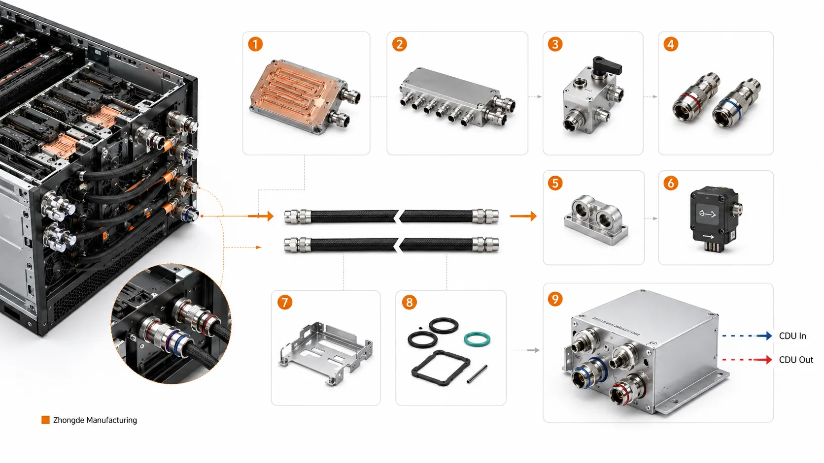
Typical server and rack liquid cooling components, including cold plates, manifolds, valve blocks, quick disconnects, hoses, seals and structural supports.
1. Defining the Liquid Cooling BOM Boundary
A liquid cooling system can be divided by location—server, rack, CDU and facility—or by function—heat collection, distribution, connection, monitoring and support. A robust BOM should identify both.
| Level | Typical Components | Main Function | Common Responsibility Boundary |
|---|---|---|---|
| Chip | CPU/GPU cold plates, TIM, mounts | Collect chip heat | Thermal performance, flatness, mounting load |
| Server | Internal manifolds, hoses, connector seats, valve blocks | Distribute coolant to cold plates | Branch flow, port position, cleanliness |
| Rack | Rack manifolds, QDs and branch tubing | Connect multiple servers | Flow balance, service access and keying |
| CDU | Pumps, heat exchanger, filters, reservoir and controls | Circulate, regulate and exchange heat | Temperature, pressure, flow and alarms |
| Monitoring | Temperature, pressure, flow and leak sensors | Detect abnormal conditions | Sensor location, thresholds and interlocks |
| Structure | Brackets, trays, enclosures and fasteners | Locate, protect and support | Dimensional chain, vibration and serviceability |
The OCP liquid cooling integration paper treats the cold plate assembly, quick connectors, hoses, brackets and server-level leak detection as one integrated delivery scope. A BOM should therefore cover more than the cold plate itself.
2. CPU and GPU Liquid Cold Plates
Cold plates are mounted directly on high-power processors. A typical cold plate contains a thermal base, internal channels or heat-transfer structures, a cover, inlet and outlet ports, sealing or joining regions and mounting features.
The component must:
- Maintain controlled contact with the chip;
- Direct coolant through the primary heat-load region;
- Meet the system pressure-drop boundary;
- Remain leak-tight under pressure and thermal cycling;
- Prevent burrs and contamination from entering the loop.
The OCP liquid cooling cold plate requirements address thermal performance, pressure drop, proof pressure, leakage, materials and reliability together. A cold plate should be validated as a functional assembly, not only as a machined part.
| Cold Plate CTQ | Main Impact |
|---|---|
| Thermal surface flatness | Contact resistance and chip load |
| Surface roughness | TIM contact condition |
| Channel width, depth and radius | Flow, pressure drop and manufacturability |
| Cover or joining surface | Sealing integrity |
| Port location and orientation | Tube assembly and mechanical load |
| Internal cleanliness | Blockage and contamination risk |
| Leak and proof pressure | Safety and long-term reliability |
3. Internal Server Manifolds
An internal server manifold divides supply and return coolant among several CPU, GPU or accelerator cold plates. It can be a separate component or integrated with valve blocks, connector seats or structural parts.
Key questions include:
- Are branch lengths and resistances balanced?
- Do different cold plates require different flow rates?
- Do the port directions match the board and hose layout?
- Are there cross-holes, plugs or cleaning dead zones?
- Are venting, draining and leak testing possible?
- Can individual cold plates or hoses be serviced?
Machined block manifolds often use aluminum or stainless steel. Their main challenges are internal deep holes, intersecting passages, plugs, valve bores, threaded ports, deburring and cleaning—not the external contour.
4. Rack Manifolds
A rack manifold distributes CDU coolant to multiple servers or compute trays and collects the return flow.
The OCP rack manifold guidelines address rack load, branch distribution, quick connections, leakage and qualification. Rack manifolds have more branches, longer flow paths, varying elevations and higher service frequency than server manifolds.
IIJ’s overview of deployed DLC equipment also notes that rack manifolds may extend through almost the full rack height and require additional side space. Existing racks may therefore need greater width or depth, or an extension frame. Its examples of approximately 42U height and 50 mm diameter are not universal design rules, but they show why the manifold envelope and service space must be reviewed during rack planning rather than added after the server design is frozen. IIJ: Frontiers of Data Center Cooling
| Rack Manifold Item | Required Definition |
|---|---|
| Total flow | Full-rack supply and return capacity |
| Branch flow | Distribution to individual servers |
| Pressure boundary | Operating, transient and proof pressure |
| QD location | Service clearance, direction and keying |
| Vent and drain | Air removal and maintenance draining |
| Support | Filled weight, vibration and shipping load |
| Installation envelope | Rack height, side clearance, extension frame and service aisle |
| Cleanliness | Particle control across long multi-branch passages |
The rack-to-server connection must be checked in the assembled rack. Individual hole-position conformity does not prove that a server can connect without side load or interference. Filled weight, QD insertion force and shipping vibration should be reacted by the support structure rather than by the fluid lines.
5. Quick Disconnects, Hoses and Rigid Tubing
Quick disconnects allow servers or compute trays to be serviced with limited fluid loss and air entry.
Important parameters include:
- Rated flow and pressure drop;
- Operating and proof pressure;
- Connection-cycle life;
- Residual fluid after disconnection;
- Locking and accidental-release prevention;
- Supply and return keying;
- Seal compatibility with coolant;
- Orientation and service clearance.
OCP blind-mate liquid connector specifications treat low-drip or dripless connection as an important rack interface. IIJ notes that couplers based on the UQD, or Universal Quick Disconnect, specification are commonly used at rack-manifold connections to support fast servicing while limiting leakage during disconnection. IIJ: Frontiers of Data Center Cooling
The QD may be a standard purchased item, but system reliability depends on the complete QD, connector seat, mounting plate and manifold interface. Errors in seat coaxiality, face position, mounting stiffness or engagement depth can create excessive insertion force, incomplete valve opening, mechanical side load or increased residual fluid even when the connector itself conforms.
Hoses absorb assembly tolerance and service movement. Rigid tubes provide controlled routing. Both require bend-radius control, support locations, abrasion protection and limits on mechanical load transferred to fittings.
6. Coolant Distribution Units
A CDU interfaces the technology cooling loop with facility cooling. It is more than a heat exchanger and performs three groups of functions:
- Transfers heat between two liquid loops without mixing the fluids;
- Circulates and controls technology-side coolant temperature, flow and pressure;
- Monitors abnormal conditions and manages filtration, filling, venting, alarms and system interlocks.
Primary-side and secondary-side terminology is not consistent across all publications. Some sources call the server loop the primary side, while others call the facility loop the primary side. Drawings, RFQs and test specifications should therefore state technology side / server side and facility side explicitly instead of relying only on “primary” and “secondary.” The EE Times Japan and AI Infra Lab explanations illustrate this terminology mismatch. EE Times Japan: CDU Structure and Capability AI Infra Lab: Illustrated CDU Guide
A typical CDU includes:
- A plate or other heat exchanger;
- Circulation pumps;
- Filters;
- Control valves and distribution blocks;
- Expansion or reservoir function;
- Temperature, pressure, flow and level sensors;
- Fill, vent and drain connections;
- PLC, touch interface, remote monitoring and alarms;
- Enclosure, frame and mounting structures.
EE Times Japan explains that gasketed plate heat exchangers are widely used: corrugated thin plates create alternating passages for the two fluids, providing high heat-transfer area while keeping the loops separated. AI Infra Lab groups the CDU into five functional blocks—heat exchanger, pumps, control valves, sensors and control system. This breakdown is useful in a manufacturing review because each block creates different requirements for mounting seats, valve bodies, ports, sealing faces, service clearance and structural support.
CDU placement changes the BOM boundary:
| Placement | Typical Characteristic | Structural and Manufacturing Impact |
|---|---|---|
| In-rack | Serves one rack in a compact package | Tight height and depth limits; service access, noise and vibration are more sensitive |
| In-row | Serves multiple racks from within the row | Higher flow, larger piping and stronger frame support |
| End-of-row | Located at the end of a row or in adjacent mechanical space | Easier centralized service, but longer piping and greater system pressure drop |
The OCP liquid-to-liquid CDU test methodology covers cooling capacity, flow, pressure drop, controls and test boundaries. CDU selection must therefore consider rack count, branch resistance, supply-return temperature difference, facility-water conditions and redundancy—not only nominal cooling capacity.
Data centers are designed to remain online. EE Times Japan describes representative CDU requirements including N+1 pump and power redundancy, hot-swappable modules, condensation control, pressure and flow monitoring, leak monitoring, historical data, local touch controls and remote access. Exact capacity and replacement-time requirements depend on the product, but the design implication is clear: service extraction space, bypasses, isolation valves, module replacement paths and sensor access must be designed in from the beginning.
Precision-manufactured CDU parts may include:
- Valve and distribution blocks;
- Connector and sensor seats;
- Pump, heat-exchanger and filter interfaces;
- Panels, enclosures, brackets and frames;
- Pressure-containing parts that require leak, proof-pressure or surface-treatment control.
7. Sensors and Leak Detection
Liquid cooling systems normally monitor temperature, pressure and flow and use leak detection at server, rack and CDU levels.
NVIDIA documentation for GB200/GB300 systems describes node- or tray-level cold-plate and inner-manifold leak sensing, plus rack-level leak ropes and spot sensors. This indicates that leak detection should be located near credible leak points rather than only near the CDU.
| Monitoring Item | Typical Purpose |
|---|---|
| Supply and return temperature | Confirm heat-transfer and operating limits |
| Supply and return pressure | Detect pump, valve or blockage abnormalities |
| Branch flow | Detect imbalance and local restriction |
| Leak sensors | Detect cold-plate, manifold, fitting or hose leaks |
| Fluid level or fill status | Identify fluid loss and service needs |
Sensor seats also require controlled threads, sealing surfaces, insertion depth, flow orientation and access for maintenance.
8. Brackets, Trays, Enclosures and Supports
Liquid cooling adds cold plates, coolant, tubing and manifolds, increasing weight and assembly constraints. Structural parts do not directly remove heat, but they determine whether components remain aligned and serviceable.
Key requirements include:
- Even cold-plate mounting load;
- Sufficient hose bend space;
- Stable support of filled manifolds during operation and shipping;
- Structural reaction of QD insertion force;
- Controlled drainage toward leak sensors or safe zones;
- Independent removal of cold plates, hoses, servers or manifolds.
Typical structural CTQs include mounting-hole location, datums, perpendicularity, parallelism, panel openings, bracket stiffness and corrosion-resistant finish.
9. Components Suitable for Precision Manufacturing
| Component | Typical Manufacturing Work | Key CTQs |
|---|---|---|
| Cold-plate base and cover | Channels, thermal surface, ports and joining surface | Flatness, channel geometry, cleanliness and leak integrity |
| Server manifold | Deep holes, cross-holes, valve bores and ports | Position, flow distribution, deburring and plugging |
| Rack manifold parts | Distribution blocks, end blocks and mounts | Assembly chain, branch interfaces and proof pressure |
| Valve block | Valve bores, sealing surfaces and internal passages | Coaxiality, roughness and cleanliness |
| Connector seat | Threads, sealing surfaces and locating features | Orientation, position and sealing quality |
| Sensor seat | Threads, insertion bore and flow interface | Insertion depth, sealing and flow direction |
| CDU structure | Enclosure, panels, frames and brackets | Mounting position, stiffness and finish |
Pumps, QDs, hoses and sensors are normally purchased from specialist suppliers. Precision machining companies are better positioned to manufacture cold plates, manifolds, valve blocks, connector seats and structures, then support cleaning, leak testing and dimensional validation.
10. Interfaces and Material Compatibility
Individually conforming parts do not guarantee a reliable assembly. High-risk areas are usually the interfaces.
| Interface | Critical Question |
|---|---|
| Chip to cold plate | Flatness, TIM and mounting load |
| Cold plate to hose | Fitting orientation, sealing and bending load |
| Hose to server manifold | Length, support and abrasion protection |
| Server to rack QD | Position, insertion force and service clearance |
| Rack manifold to CDU | Tube size, pressure drop and supply-return direction |
| Sensor to valve block | Insertion depth, sealing surface and flow direction |
All wetted metals, brazing or welding materials, seals, hoses and coolant additives should be reviewed together for compatibility. Checking only the base cold-plate material is not sufficient.
IIJ notes that technology-side loops often use coolants such as PG25, an approximately 25% propylene-glycol solution, while the facility side may use managed water. That concentration is not a universal answer, but it highlights an important design rule: viscosity, heat capacity, corrosion inhibition, seal compatibility and pump pressure drop must be calculated for the actual fluid formulation rather than treating water and glycol solutions as identical. IIJ: Frontiers of Data Center Cooling
Facility-side water quality also requires control. Conductivity, pH, hardness, chloride, particles and biological condition can affect heat exchangers, valves, piping and seals. RFQs should define the fluid, concentration, water-quality limits and maintenance method for both the technology and facility loops, and should not rely only on “primary” and “secondary” labels that different suppliers may interpret in opposite ways.
11. Component Acceptance Requires Functional Tests
| Acceptance Category | Applicable Components | Main Purpose |
|---|---|---|
| Dimensions and appearance | All machined parts | Confirm installation and interfaces |
| Internal cleanliness | Cold plates, manifolds, valve blocks and tubing | Prevent particles from entering the loop |
| Leak and proof pressure | Cold plates, manifolds, fittings and assemblies | Validate sealing and strength |
| Flow and pressure drop | Cold plates, manifolds and assemblies | Detect blockage and resistance variation |
| Branch-flow balance | Multi-branch manifolds | Validate distribution consistency |
| Connection durability | QDs and mounting structures | Validate service reliability |
| Thermal performance | Cold plates and server assemblies | Confirm temperature rise or thermal resistance |
| Sensor function | CDU and monitoring assemblies | Validate alarms and controls |
| Redundancy and failover | CDU pumps, power supplies and control modules | Validate N+1 transfer, bypass and online service |
| Operational monitoring | CDU and system assembly | Validate temperature, pressure, flow, leak, history and remote alarms |
| Condensation prevention | CDU and supply control | Validate margin between coolant supply temperature and ambient dew point |
A passing leak test only confirms that no external leakage was detected under the specified condition. It does not prove that channels are clear, branch flow is balanced or thermal performance is acceptable. CDU validation should also cover pump or power failure transfer, alarm history, remote access, valve isolation and recovery after maintenance.
12. RFQ Checklist for Server Liquid Cooling Components
Provide system, component and validation information together.
| Information Category | Recommended Input |
|---|---|
| System connection diagram | Relationship between cold plates, manifolds, QDs and CDU |
| BOM | Part name, quantity, material, supply responsibility and revision |
| Controlled drawings | 2D, 3D, datums, tolerances and CTQs |
| Fluid conditions | Coolant, temperature, target flow and pressure-drop limit |
| Pressure conditions | Operating, peak, proof pressure and leak rate |
| Interfaces | Threads, QDs, hoses, sensors and orientation |
| Cleanliness | Particle, residue, cleaning and packaging requirements |
| Surface treatment | Anodizing, plating, corrosion protection and masking |
| Validation | Dimensional, leak, proof, flow, thermal and reporting requirements |
| Project conditions | Prototype quantity, forecast volume, lead time and change control |
A complete BOM reduces gaps between suppliers. When the design is still under development, at least provide a connection diagram and define the functional boundary of each part.
Frequently Asked Questions
What are the core components of a server liquid cooling system?
In a direct-to-chip system, the core components are the cold plates that absorb heat from CPUs and GPUs, the server and rack manifolds that distribute supply and return coolant, and the CDU that circulates coolant and transfers heat. Quick disconnects, hoses, sensors, leak detection and mounting structures are also essential to safe service and stable operation.
What is the difference between a server manifold and a rack manifold?
A server manifold is located inside one server or compute tray and distributes coolant to several CPU, GPU or accelerator cold plates. A rack manifold runs along the rack, distributes coolant from the CDU to multiple servers and collects their return flow. Their flow capacity, number of ports, installation space and manufacturing structure are different.
Why are quick disconnects important in liquid cooling?
Quick disconnects allow a server or compute tray to be removed for service with minimal coolant loss. Sealing, pressure drop, connection life, orientation, residual fluid and installation position all affect reliability, so they should not be treated as ordinary pipe fittings.
Is a complete BOM required to quote liquid cooling components?
A complete BOM is preferred. At minimum, provide a system connection diagram, 2D drawings, 3D models, interface specifications, coolant type, target flow, allowable pressure drop, operating pressure, leak-rate requirement, cleanliness, surface treatment, prototype quantity and expected production volume. The connection and functional boundary of each part should be clear.
