
In This Article
Direct Answer
The key manufacturing change created by Co-Packaged Optics (CPO) is not simply “a smaller optical module.”
It is a relocation of the optical boundary:
Traditional
Switch ASIC
  ↓ longer high-speed electrical path
Faceplate
  ↓
Pluggable Optical Module
  ↓
Fiber

CPO
Switch ASIC
  │
  ├─ Optical Engine
  │      ↓
  └──── Fiber Array / FAU
         ↓
      Front Panel / Backplane
Corning stated in July 2026 that NPO and CPO push fiber beyond the faceplate and terminate it within millimeters of silicon. Broadcom defines CPO as heterogeneous integration of optics and switch silicon on a common packaged substrate.
The mechanical value therefore moves as well:
less dependence on a standalone small module housing
→ more value in optical-engine carriers, heat spreaders, cold plates, fiber management and system datums.
This article cross-checks public information searched in English, Chinese, Japanese, German and French through August 2026, with emphasis on Corning, Broadcom, NVIDIA, TrendForce, TE Connectivity, GlobalFoundries and Fraunhofer. CPO implementations differ in optical source, cooling method, fiber attach and service boundary. No single vendor architecture should be treated as an industry-wide mechanical standard, and nothing here implies a supply relationship between Zhongde and the companies discussed.
Corning: Why Scalable CPO Must Be Built as a System
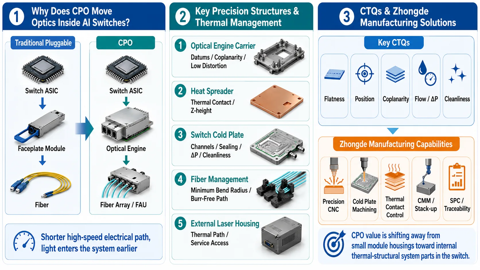
1. Why Is Optics Moving Inside the Switch?
A traditional pluggable optical module has a clear mechanical boundary:
Switch ASIC
→ high-speed PCB traces
→ front-panel connector / cage
→ optical module
→ fiber
The architecture is serviceable and benefits from a mature multi-vendor ecosystem.
The problem becomes harder as SerDes lane rates and switch capacity rise. The electrical path between the ASIC and faceplate includes PCB length, vias, connectors, cages and module interfaces. More path loss and reflections require more equalization and often DSP or retiming, adding power and heat.
CPO shortens that path by moving the optical engine onto the same package substrate or very close to the switch ASIC:
End the high-speed electrical path earlier and let light carry the longer distance.
Broadcom has publicly shipped 51.2T and 102.4T CPO platforms and identifies path loss, power and bandwidth density as major drivers.
2. CPO Redraws the Mechanical Boundary
Traditional pluggable optics concentrate mechanical value in:
- upper and lower housings;
- precision bases;
- heatsinks;
- faceplate interfaces;
- pull-tab and latch mechanisms;
- EMI and grounding contacts.
CPO moves part of that functionality into the switch.
| Architecture Boundary | Pluggable | CPO Shift |
|---|---|---|
| Electro-optical conversion | Front-panel module | Optical engine near ASIC |
| Thermal management | Per-module | ASIC + optical engine co-design |
| Fiber entry | Directly into module | Fiber/FAU routes inside chassis |
| Mechanical datum | Module envelope and cage | Package, carrier, cold plate and chassis |
| Service boundary | Replace one module | Optical engine, laser, fiber and system service |
| Precision metal parts | Housing, base, heatsink | Carrier, heat spreader, cold plate, supports |
CPO therefore does not mean “the housing disappears.”
It means:
mechanical value moves from a standalone small module into a more integrated optical–thermal–mechanical switch system.
3. Three Production Barriers Recur Across Five-Language Research
3.1 Fiber Alignment
TrendForce’s 2026 CPO production research identifies fiber alignment, thermal management and testing cost as core ramp barriers.
Fraunhofer’s PIC packaging work similarly highlights accurate PIC-to-fiber and laser-to-PIC alignment and thermal sensitivity.
A crucial manufacturing distinction is:
final optical coupling accuracy is not the same as the required accuracy of a metal CNC carrier.
Fine coupling is normally created by photonic packaging, active/passive alignment, flip-chip and dedicated optical assembly. A machined carrier provides a stable first-level mechanical datum that protects this fine alignment from warpage, clamping and thermal cycling.
3.2 Thermal Management
CPO moves temperature-sensitive optical devices next to a high-power switch ASIC:
High-power Switch ASIC
        ↓
Shared package / nearby structure
        ↓
PIC / EIC / Optical Engine
The problem is no longer “cool each pluggable module.” It becomes:
ASIC + Optical Engine + Package + Heat Spreader / Cold Plate co-design.
Broadcom lists thermal design among the improvements required for CPO manufacturing maturity. NVIDIA has gone further by publishing liquid-cooled CPO switches where switch silicon and onboard photonics are cooled within one integrated thermal architecture.
NVIDIA: Silicon Photonics Networking
3.3 Fiber Routing
Corning argues that CPO must be engineered from faceplate to silicon as one system. TE Connectivity’s 2026 OFC demonstrations combine CPO/NPO sockets, FAUs, external-laser interfaces, optical backplanes and liquid cooling.
Fiber management therefore affects bend radius, strain, connector service, cold-plate clearance, tubing clearance, assembly order and chassis space.
4. Which Precision Structures Are Real Manufacturing Opportunities?
| Part | Main Function | CNC Fit | Manufacturing View |
|---|---|---|---|
| Optical Engine Carrier / Frame | First-level mechanical datum | High | Stable datums, coplanarity, stiffness, low distortion |
| Heat Spreader / Thermal Lid | Transfer heat to heatsink/cold plate | High | Contact surface and Z-height dominate |
| Switch Cold Plate | Cool ASIC and nearby high-heat components | High | Channels, flatness, sealing, pressure drop, cleanliness |
| Liquid-Cooling Interface Block | Connect cold plate to loop/manifold | High | Port position, sealing and internal passages |
| External Laser Source Housing | CW laser structure and thermal path | Medium-High | Thermal interface, connector and serviceability |
| Fiber Management Metal Frame | Route and protect fiber | Medium | Burr-free path, stiffness and service space |
| FAU Fine-Alignment Structure | Final optical coupling | Low-Medium | Dominated by photonic packaging processes |
| Chassis / Faceplate | System envelope | Medium-Low | Sheet metal/die casting dominate; CNC only critical datums |
The right target for a precision manufacturer is not “nanometer-level PIC alignment.”
It is:
a mechanically and thermally stable reference system that preserves the alignment created by the photonics packaging process.
5. Optical Engine Carrier CTQs
| CTQ | Why It Matters |
|---|---|
| Datum flatness | Controls engine attitude and local load |
| Coplanarity | Controls Z-height across multiple engines |
| Pocket depth / step height | Sets engine-to-package and thermal stack |
| Hole position | Affects assembly and connector path |
| Free-state warpage | Prevents fixture-induced false acceptance |
| Final dimension after finish | Anodizing/plating can shift fits and height |
| Stiffness | Cold-plate or assembly load must not distort datum |
| Cleanliness / burrs | Sensitive proximity to optical assemblies |
The goal is not to tighten every dimension.
A better sequence is:
Optical Engine
↓
Functional interfaces
↓
Assembly stack
↓
True CTQs
↓
Economic tolerance on non-critical geometry
6. Why Heat Spreaders and Cold Plates Become Central Parts
The thermal design has two competing objectives:
- remove large ASIC heat loads rapidly;
- keep optical-engine temperature behavior controlled and predictable.
The goal is not simply “maximum cooling.”
It is:
low thermal resistance where heat is high + controlled optical-engine temperature + limited thermo-mechanical distortion.
Heat-Spreader CTQs
- thermal contact flatness;
- surface roughness;
- local step height;
- coplanarity across contact zones;
- material thickness;
- copper/aluminum interface;
- coating/TIM compatibility;
- distortion under assembly load.
Switch Cold-Plate CTQs
- ASIC thermal-contact flatness;
- thermal Z-height around optical engines;
- channel geometry;
- seal grooves;
- inlet/outlet position;
- leak and proof pressure;
- flow and pressure drop;
- internal burrs and particles;
- residual cleaning fluid;
- coolant/material compatibility.
NVIDIA’s Q3450-LD is a useful real-world example. It uses two parallel liquid-cooling loops and publishes product-specific flow, pressure, pressure-drop, filtration and coolant requirements.
Those values are not universal CPO specifications, but they prove that the CPO switch cold plate is already a real production system component.
NVIDIA Q3450-LD Liquid-Cooling System
7. Fiber Management CTQs Are Different From Ordinary Cable Brackets
Fiber routing must control:
- customer-defined minimum bend radius;
- fiber direction before FAU/connector entry;
- slack;
- clamp position;
- strain relief;
- clearance from cold plates, UQDs, tubing and PCB;
- assembly and service path;
- burr-free and rounded contact edges;
- contamination protection at optical interfaces.
Fraunhofer research on board-level optical interconnects notes that fiber count and routing/slack-management space increase as CPO bandwidth scales.
The most important CTQ may therefore not be a ±0.01 mm dimension.
It may be:
stable routing without fiber damage, with serviceability and coexistence with the cooling system.
8. Three Levels of “Precision” in CPO
Level 1: Photonic Alignment
Handled by optical packaging:
- PIC ↔ FAU;
- Laser ↔ PIC;
- waveguide coupling;
- active alignment.
Level 2: Precision Mechanical Datum
A strong CNC opportunity:
- carrier datum;
- cold-plate datum;
- heat-spreader Z-height;
- chassis/mid-plate position;
- fiber connector support;
- external-laser interface.
The purpose is to keep Level 1 stable.
Level 3: System Envelope
Often handled by:
- sheet metal;
- die casting;
- extrusion;
- injection molding;
- structural assembly.
CNC should be concentrated on functional interfaces.
9. Failure–Cause–Countermeasure Matrix
| Failure | Possible Cause | Manufacturing Countermeasure |
|---|---|---|
| Optical-engine attitude shift | Carrier warpage or stack-up | Free-state inspection, functional datums, CMM |
| High thermal resistance / hotspot | Non-flat spreader or cold plate | Contact-zone flatness and assembly-state validation |
| Link drift after temperature change | CTE mismatch, thermal gradient | Material/structure review, post-cycle verification |
| Fiber micro-bend loss | Excess clamp force, tight radius | Route gauges, rounded edges, assembly standard |
| Fiber damage | Burrs, sharp edges, particles | Deburring and optical-zone cleanliness |
| Cold-plate ΔP drift | Channel variation or contamination | Channel CTQ, cleaning, flow/ΔP test |
| Leak | Seal groove, port or joining defect | Seal dimensions, leak/proof test, traceability |
| Post-finish assembly interference | Coating not included in stack | Masking, process compensation, final inspection |
| Grounding problem | Anodizing over contact area | Defined conductive zones and masking validation |
10. How CPO Changes the Production Economics
Traditional optics:
one module
→ one small housing
→ one heatsink
→ front-panel replacement
CPO:
one switch package
→ multiple optical engines
→ shared carrier / mid-plate
→ shared heat spreader / cold plate
→ multiple FAU / fiber harnesses
→ external laser
→ system-level cooling and service
Part count may not simply explode because integration removes many standalone modules.
But the functional value per precision structure rises.
A carrier or cold plate may affect many optical engines, the switch ASIC, fiber routing and system reliability at the same time.
The attractive manufacturing target becomes:
high-function, stable-version thermal/mechanical parts that repeat in volume.
11. Where Zhongde Fits
Zhongde should not position itself as a PIC/EIC/FAU photonic-packaging supplier.
A more credible position is:
precision metal structures and thermal-management manufacturing for CPO systems.
Optical Engine Carrier / Precision Frame
Relevant capabilities include:
- precision aluminum CNC;
- multi-datum machining;
- thin-wall and low-distortion process planning;
- position and coplanarity control;
- final inspection after surface treatment;
- CMM stack-up verification.
Heat Spreader / Thermal Base
- thermal-contact finishing;
- flatness and roughness;
- local step height;
- copper/aluminum structures;
- masking and surface treatment;
- free-state vs assembled-state definition.
Switch Cold Plate / Liquid Interface
Project-specific evaluation can cover:
- CNC channels;
- base/cover geometry;
- seal grooves;
- interface blocks;
- deburring and cleaning;
- leak/proof and flow/pressure-drop CTQs;
- liquid-cooling structural assembly.
Joining and test methods should follow the customer’s approved structure and validation specification.
Fiber-Management Metal Structure
- metal guide frames;
- FAU/connector support;
- high-stiffness internal brackets;
- cold-plate/tubing clearance;
- burr-free radii;
- assembly datums and gauges.
Final active optical alignment should not be misrepresented as a generic CNC capability.
12. Recommended Manufacturing Control Chain
Customer optical / thermal architecture
↓
Identify optical, thermal and fiber functional boundaries
↓
CTQ + datum review
↓
DFM and process route
↓
Prototype
↓
Free-state dimensional + assembly-state validation
↓
Surface treatment
↓
Final dimension / flatness / cleanliness
↓
Cold-plate functional test when applicable
↓
DVT / PVT
↓
SPC + traceability| CTQ Layer | Primary Manufacturing Control |
|---|---|
| Mechanical | Flatness, position, coplanarity, Z-height, warpage |
| Thermal | Contact surfaces, TIM interface, channels, flow/ΔP |
| Liquid | Seal groove, leak, proof pressure, cleanliness |
| Fiber-Safe | Route, radius, burrs, clamp interface, connector support |
| Surface | Coating thickness, masking, conductive zones |
| Production | Fixtures, tool life, SPC, lot traceability, change control |
13. RFQ Inputs That Matter
| Input | Recommended Information |
|---|---|
| Architecture | CPO/NPO type, number/location of optical engines |
| Datum | Functional package/carrier/cold-plate/chassis datums |
| Optical Boundary | FAU/fiber/connector position and routing requirements |
| Thermal | ASIC/OE power, hotspot, TIM and thermal limits |
| Cold Plate | Coolant, flow, ΔP, pressure, leak, cleanliness |
| Materials | Aluminum, copper, stainless, coating/plating |
| Surface | Thermal contact, grounding, masking, wetted surfaces |
| State | Free-state vs assembled-state acceptance |
| Reliability | Thermal cycle, vibration, fiber service cycle |
| Volume | Prototype, EVT/DVT/PVT, annual volume, SPC |
A good DFM process does not begin by making every dimension ultra-tight.
It begins by identifying the few features that directly control optical, thermal, liquid and assembly function.
Frequently Asked Questions
Why does CPO move the optical engine from the switch faceplate toward the ASIC?
The main reason is to shorten the high-speed SerDes electrical path. In a traditional pluggable architecture, signals travel from the switch ASIC through PCB traces, connectors and the faceplate before entering the optical module. As lane rate rises, insertion loss, equalization and power become harder to manage. CPO places the optical engine on the same package or very close to the ASIC so electrical signals are converted to light much earlier.
Will CPO eliminate CNC demand for traditional optical-transceiver housings?
Not immediately. Pluggable optics, LPO, NPO and CPO will coexist because different network layers and service models need different architectures. In a true CPO switch, however, the value of the front-panel module housing declines while mechanical value shifts toward optical-engine carriers, heat spreaders, cold plates, fiber-management structures, external-laser structures and system-level mounting interfaces.
Does CPO optical alignment require metal CNC parts with nanometer-level accuracy?
That is generally the wrong interpretation. Final PIC-to-FAU optical coupling normally depends on photonic packaging, active or passive optical alignment, dedicated assembly equipment and bonding or joining processes. General metal CNC parts are more valuable as stable first-level datums that control flatness, position, stiffness and thermal stability so the fine optical alignment is not disturbed later.
Why do switch cold plates and liquid-cooling interfaces become more important with CPO?
When optical engines move next to a high-power switch ASIC, the ASIC, optical devices and nearby electronics enter a tightly coupled thermal zone. Some CPO products can use advanced air cooling, but NVIDIA has publicly introduced liquid-cooled CPO switches that cool onboard silicon photonics in the same thermal architecture. Cold-plate flatness, channels, pressure drop, sealing, cleanliness and material compatibility can therefore become system-level CTQs.
What are the most common precision-structure failure modes in CPO production?
Typical risks include carrier warpage changing optical-engine attitude and thermal contact, non-flat heat spreaders or cold plates creating uneven TIM thickness, coating thickness shifting the Z-height stack, burrs on fiber guides causing micro-bending or damage, clamps adding fiber stress, particles or residual liquid affecting cold-plate flow, and thermal cycling causing relative movement between dissimilar materials.
What should be included in an RFQ for CPO-related precision structures?
Provide 2D drawings, 3D models, the location of the part in the switch ASIC–optical engine–fiber path, mechanical datums, assembly Z-height, heat sources and thermal path, TIM conditions, cooling method, cold-plate flow and allowable pressure drop, leak and proof-pressure requirements, cleanliness, fiber routing and minimum bend-radius requirements, surface treatment, conductive or masked regions, free-state or assembled-state acceptance conditions, prototype quantity, expected annual volume and reliability-validation requirements.
