
In This Article
Direct answer
Pluggable optics, LPO, NPO and CPO are often drawn on one technology roadmap, but they do not describe exactly the same design dimension.
Signal-processing boundary:
Retimed Pluggable → LPO / LRO

Physical optical-engine location:
Front-panel Pluggable → NPO → CPO- Retimed Pluggable: the DSP or retimer, drivers, TIAs, optical engine and fiber interface are inside a front-panel module.
- LPO: the module remains front-panel pluggable but uses a linear electrical interface and normally removes the full module retimer.
- NPO: the optical engine moves from the front panel to the board near the ASIC but remains a separate board-level unit.
- CPO: optical engines and the switch or compute ASIC share the same package or package substrate.
| Comparison | Retimed Pluggable | LPO | NPO | CPO |
|---|---|---|---|---|
| Optical location | Front panel | Front panel | Board near ASIC | Same package as ASIC |
| Full module retimer | Usually present | Usually absent | Architecture dependent | Usually short linear interfaces |
| Electrical path | Longest | Relatively long | Short | Shortest |
| Replaceability | High | High | Medium and design dependent | System-level service |
| Thermal boundary | Individual module | Module and host co-design | ASIC plus board optical engine | ASIC, engines, package and cold plate co-design |
| Typical precision parts | Housing, lid, heatsink and latch | Housing and redistributed thermal structures | Engine mounts, fiber supports and miniature thermal parts | Cold plates, engine carriers, liquid interfaces and external-laser housings |
| Ecosystem maturity | Highest | Expanding deployment | Evaluation and introduction | Productized, but system implementations vary |
OIF current work applies 224G linear electrical interfaces to LPO, NPO and CPO. The OIF Compute Optics Interface white paper defines LPO as a linear front-panel pluggable module and describes NPO as optics near an ASIC without common packaging. Broadcom defines CPO as heterogeneous integration of optics and silicon on one packaged substrate.
Information boundary: This article uses OIF, Broadcom, NVIDIA and other public technical information available through August 2026. Suppliers may implement LPO, LRO, NPO and CPO differently, and a public demonstration or announcement does not mean that every architecture is deployed at scale. The article does not imply a supply relationship between Zhongde and any company mentioned.
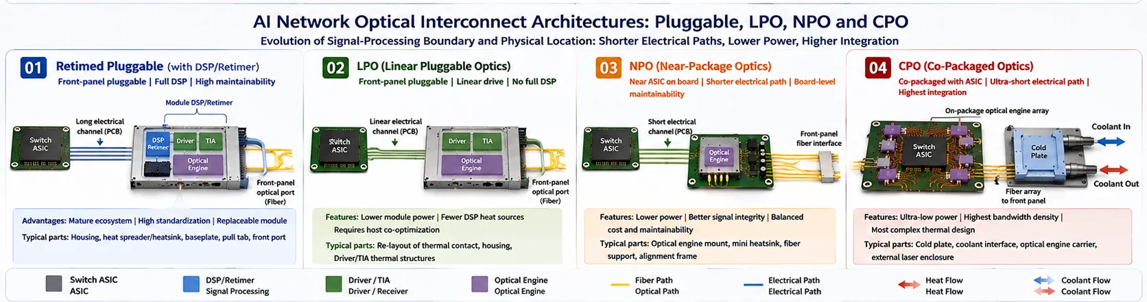
1. Why is AI networking reconsidering where optics should be placed?
In a conventional switch, the switch ASIC is near the center of the board while optical modules sit at the front panel. A high-speed SerDes signal travels through:
Switch ASIC
→ PCB trace
→ vias and connector
→ front-panel cage
→ module electrical interface
As lane rates rise from 100G to 200G and beyond, insertion loss, crosstalk, equalization and power become harder to manage. Conventional modules commonly use DSPs or retimers to recover and reshape the signal.
The basic ways to shorten or simplify the electrical path are:
- redefine how much signal processing occurs inside the module;
- move the optical engine away from the front panel and closer to the ASIC;
- place the optical engine inside the same package boundary as the ASIC.
Moving optics closer to the ASIC also moves it closer to the hottest and least serviceable part of the system. The electrical benefit therefore transfers complexity into cooling, packaging, fiber management, yield and service.
2. Why do retimed pluggable modules remain important?
A typical path is:
Switch ASIC
→ relatively long PCB channel
→ front-panel connector
→ module DSP / retimer
→ driver / TIA
→ optical engine
→ fiber
2.1 Main advantages
- field replacement and hot-plug service;
- a mature OSFP, QSFP-DD and related ecosystem;
- a clear design and test boundary for module suppliers;
- a failed module can be replaced without replacing the switch ASIC;
- more mature multi-vendor interoperability and inventory management;
- optical-package yield is not fully absorbed by the system ASIC package.
2.2 Precision-structure demand
Retimed pluggable modules still require:
- upper and lower housings and a precision base;
- thermal lids and heat spreaders;
- module or host heatsinks;
- pull tabs, latches and insertion structures;
- front-panel and optical-port features;
- grounding and EMI contact areas;
- assembly, insertion and thermal-test fixtures.
This remains the most direct connection to Zhongde’s current optical-transceiver structural-part capabilities.
3. What does LPO change?
LPO means Linear Pluggable Optics. It stays at the front panel and may retain OSFP or another pluggable form factor, but its electrical chain differs from a retimed module.
Switch ASIC SerDes
→ linear PCB channel
→ driver / TIA
→ optical devices
→ fiber
OIF defines LPO as a linear front-panel pluggable module, emphasizing a more direct electrical-to-optical mapping rather than a complete module retimer.
3.1 LPO is more than removing a DSP
Reducing the module DSP can lower:
- module power;
- the DSP hotspot;
- latency;
- some component cost.
However, the complete system must jointly control:
- host SerDes performance;
- PCB material, length, vias and connector loss;
- driver and TIA linearity;
- optical-device bandwidth and noise;
- channel-to-channel consistency;
- system test, calibration and interoperability.
LPO therefore transfers part of the module complexity into the full host link.
3.2 Mechanical and manufacturing impact
- thermal-contact steps change when the DSP hotspot is removed;
- driver, TIA and optical-engine heat paths become more important;
- PCB-to-housing alignment may become more sensitive;
- lower total power does not prove that every local hotspot is lower;
- thermal consistency can affect linear-link margin;
- the housing, pull tab, latch, shielding and insertion tolerance chain remain necessary.
4. Where does NPO place the optical engine?
NPO means Near-Package Optics. It puts an independent optical engine on the board near a switch ASIC, GPU or other compute device without sharing the same package.
Switch ASIC / GPU
→ short PCB electrical channel
→ board-mounted optical engine
→ fiber
→ front-panel fiber interface
4.1 The NPO compromise
NPO aims to combine:
- a shorter electrical path than a front-panel module;
- less package coupling than CPO;
- some possibility of board-level assembly, replacement or service.
The actual serviceability depends on the design. A soldered, socketed, screw-mounted or modular optical engine creates a different maintenance boundary.
4.2 Precision-manufacturing opportunities
- precision optical-engine mounts;
- board-level locating frames;
- miniature heat spreaders and heatsinks;
- fiber-array retention;
- fiber strain relief and bend-radius supports;
- removable engine retention mechanisms;
- assembly fixtures linking ASIC, engines and cooling structures;
- board-level location and dimensional inspection fixtures.
The complete module housing may become smaller or disappear, but board-level datums, thermal parts and fiber mechanical structures become more important.
5. How is CPO different from a conventional optical module?
CPO means Co-Packaged Optics. Broadcom describes it as heterogeneous integration of optics with a switch ASIC or XPU on one package substrate.
Switch ASIC
↔ very short electrical interconnect
↔ multiple in-package optical engines
→ dense fiber connectivity
→ external or integrated laser
Broadcom CPO switches integrate optical engines for direct high-speed connectivity to high-bandwidth switch ASICs. NVIDIA Spectrum-X and Quantum-X Photonics similarly integrate silicon-photonics engines around the switch ASIC.
5.1 What problem does CPO address?
- shorter high-speed electrical paths;
- lower interconnect power per bit;
- higher front-panel and package bandwidth density;
- reduced dependence on high-loss copper links;
- scaling of very large AI cluster networks.
5.2 What new problems does CPO introduce?
- the ASIC and optical engines generate heat in the same package region;
- optical devices sit close to a high-power chip;
- optical-engine and ASIC yield boundaries become coupled;
- fiber count, density and service complexity increase;
- external lasers require separate thermal control and service strategy;
- package substrate, cold plate and optical engines must be co-designed;
- service no longer means pulling one front-panel module.
NVIDIA states that its Quantum-X Photonics switch uses liquid cooling for onboard silicon photonics and a field-replaceable external laser source. CPO therefore expands an optical-module problem into a system-level optical, electrical, thermal, fluid and service problem.
6. Where is the laser located?
| Architecture | Typical laser location | Structural impact |
|---|---|---|
| Retimed Pluggable | Inside module | Hotspots remain inside a clearly serviceable module |
| LPO | Primarily inside module | Laser and driver heat paths become more visible after DSP reduction |
| NPO | Inside optical engine or as a board unit | More board-level fiber and retention structures |
| CPO | Integrated or external laser source | External-laser housing, thermal control and dense fiber delivery may be required |
An external laser source can be a separate, replaceable system unit that needs stable temperature, precise fiber output and protection. It therefore creates new needs for metal housings, thermal spreaders, fiber exits and assembly structures.
7. How does the thermal boundary change?
7.1 Retimed Pluggable and LPO
Typical path:
DSP / driver / laser / optical engine
→ module thermal lid
→ TIM
→ system heatsink
→ airflow
LPO redistributes the hotspots after removing the DSP, but most cooling remains across the module-to-host-heatsink boundary.
7.2 NPO
Typical path:
Board-mounted optical engine
→ miniature heatsink or spreader
→ board airflow or local cooling structure
The optical engine sits closer to the ASIC, so cooling must prevent ASIC heat from destabilizing the optics.
7.3 CPO
Typical path:
ASIC + in-package optical engines
→ common or zoned thermal interfaces
→ cold plate
→ liquid loop
A CPO cold plate must consider more than the center ASIC hotspot:
- optical-engine temperature;
- several contact-height zones;
- package and cold-plate assembly warpage;
- fiber exit clearance;
- liquid connectors and channels;
- leakage risk;
- service and replacement sequence.
8. Which precision-manufacturing opportunities increase?
8.1 Pluggable and LPO
- upper and lower housings;
- thermal lids;
- aluminum or copper heatsinks;
- precision bases;
- pull-tab and latch mechanisms;
- front-panel and optical-port structures;
- EMI and ground regions;
- assembly and inspection fixtures.
8.2 NPO
- optical-engine mounts;
- board-level locating frames;
- miniature heatsinks;
- local heat spreaders;
- fiber retention and strain-relief parts;
- removable retention mechanisms;
- board assembly and inspection fixtures.
8.3 CPO
- cold plates around ASICs and optical engines;
- liquid-interface bases;
- optical-engine carriers;
- external-laser metal housings;
- fiber-array supports and protection;
- switch cooling manifolds;
- high-cleanliness assembly structures;
- flow, pressure, leakage and assembly-test fixtures.
The central shift is:
As optics move toward the ASIC, the share of a small complete module housing may decrease, while the value of system cold plates, engine carriers, fiber supports and assembly fixtures rises.
9. Which characteristics are true CTQs?
| CTQ | Pluggable / LPO | NPO / CPO |
|---|---|---|
| Thermal-contact height | Module lid and TIM | Multiple ASIC, engine and cold-plate zones |
| Flatness | Module thermal lid | Large cold plate and local mounting datums |
| Optical-port location | Front-panel connector | Dense fiber arrays and board exits |
| Envelope | Cage insertion | Board, package, cold plate and fiber space |
| Assembly warpage | Module housing | Package substrate, engines and cold plate |
| Cleanliness | Optical ports and thermal interfaces | Engines, package, fibers and fluid channels |
| Leak, pressure and flow | Normally outside module body | Cold plates, connectors and manifolds |
| Service interface | Pull tab and latch | Removable engines, external lasers and system units |
CTQs should be defined by functional loops rather than by tightening every dimension equally.
10. Which prototype assumptions commonly fail?
10.1 LPO mistakes
- assuming that removal of the DSP automatically simplifies the module;
- validating the module without the host SerDes and PCB channel;
- ignoring temperature effects on linear-link margin;
- failing to redefine thermal-contact steps.
10.2 NPO mistakes
- treating NPO as a smaller version of CPO;
- locating the engine without solving fiber bending and service;
- relying on manual fiber routing that cannot repeat in production;
- failing to define the final board-level inspection datum.
10.3 CPO mistakes
- calculating ASIC power without optical-engine and laser heat;
- verifying free-state cold-plate flatness but not assembled warpage;
- checking flow without measuring zoned temperatures;
- allowing fiber exits to conflict with cold plates, fittings or chassis;
- failing to define separate acceptance ownership for package, cold plate, external laser and complete system.
11. How should the design move from prototype to production?
A practical route is:
Confirm architecture and service boundary
→ freeze ASIC, engine, laser and fiber locations
→ review thermal and fluid concept
→ establish CTQs and assembly tolerance chains
→ build all-CNC structure and cold-plate prototypes
→ validate optical, electrical, thermal, fluid and service functions
→ select blanks and production processes
→ machine critical functional surfaces
→ finish, clean and assemble
→ run pilot production and capability review
→ stabilize production and change control
CPO manufacturing validation may need to cover:
- dimensions and geometric tolerances;
- cold-plate flatness;
- leak and proof pressure;
- flow and pressure drop;
- cleanliness;
- fiber protection;
- assembled warpage;
- batch traceability.
12. Where can Zhongde participate?
12.1 Suitable scope
- aluminum and copper structures around modules and optical engines;
- thermal lids, spreaders and miniature heatsinks;
- liquid cold plates around ASICs and optical engines;
- liquid interfaces, manifolds and structural bases;
- external-laser metal housings;
- fiber retention, protection and strain-relief structures;
- CNC finishing of cast, extruded, forged and other near-net blanks;
- anodizing, electroless nickel, coating and local masking;
- deburring, cleaning, assembly, protective packaging and traceability;
- CMM, leak, pressure, flow and assembly validation;
- process transfer from engineering prototypes to stable batch production.
12.2 Scope that should not be overstated
Zhongde should not claim to provide:
- switch ASIC, DSP, SerDes or high-speed PCB design;
- silicon-photonics PIC, laser or wafer manufacturing;
- advanced semiconductor packaging;
- active fiber alignment and core optical packaging;
- complete LPO, NPO or CPO system certification;
- IEEE, OIF or MSA certification;
- an existing supply relationship with Broadcom, NVIDIA or other companies named.
13. What inputs should an RFQ include?
| RFQ input | Purpose |
|---|---|
| Architecture type | Distinguish retimed, LPO, NPO or CPO |
| ASIC, optical-engine and laser location | Define electrical, thermal and structural boundaries |
| 2D drawings and 3D assembly | Build datums and tolerance chains |
| Heat-source power and temperature limits | Define thermal interfaces and cold-plate zones |
| Fiber count, exits and bend limits | Design retention, protection and service space |
| Coolant, flow, pressure and pressure drop | Design channels, fittings and validation |
| Key CTQs | Build machining and inspection plans |
| Finishing and masking zones | Protect thermal, ground and fluid interfaces |
| Assembly and service method | Define removable boundaries and acceptance state |
| Prototype and annual volume | Select all-CNC or near-net production route |
| Cleanliness, packaging and traceability | Protect optical and fluid systems |
Frequently asked questions
What are the main differences among LPO, NPO and CPO?
LPO is a linear front-panel pluggable optical module and primarily changes the signal-processing boundary inside the module. NPO places an independent optical engine on the board near the ASIC. CPO integrates the optical engine with the ASIC on the same package or package substrate. LPO emphasizes a pluggable module, NPO emphasizes near-package placement with board-level separation, and CPO emphasizes common packaging, so they are not simply three consecutive generations.
Is LPO only a pluggable module with the internal DSP removed?
No. Removing or reducing the full module retimer is one visible change, but LPO also requires the host SerDes, PCB channel, connector, driver, TIA and optical devices to satisfy a shared linear link budget. Signal integrity, channel consistency, system testing and interoperability control therefore become more demanding. Internal heat sources are redistributed, but mechanical design and production validation do not automatically become simple.
Will CPO rapidly replace conventional pluggable optical modules?
Not as a simple and rapid full replacement. Pluggable optics provide mature standards, a multi-vendor ecosystem, field replacement and clear test boundaries, which remain valuable across many data-center systems. CPO is attractive where bandwidth density and interconnect power are limiting, but it introduces more difficult packaging, liquid cooling, fiber routing, external-laser, yield and service challenges. Pluggable optics, LPO, NPO and CPO are more likely to coexist in different systems.
What precision-structure and liquid-cooling opportunities can NPO and CPO create?
NPO can increase demand for optical-engine mounts, board-level locating frames, miniature heatsinks, fiber supports and removable retention mechanisms. CPO may require cold plates around the ASIC and optical engines, liquid-interface bases, optical-engine carriers, external-laser metal housings, fiber-array supports, switch cooling manifolds, assembly fixtures and high-cleanliness protective structures. The actual parts depend on the customer package, thermal design and service boundary.
