
In This Article
Direct Answer
The final appearance of an anodized fishing reel part is not created only in the anodizing tank.
Material condition, CNC tool marks, polishing or blasting, pretreatment, anodic coating, coloring, sealing, rack contact and part geometry all influence the final visual result.
Therefore:
same nominal color does not automatically mean the same appearance.
For frames, side plates, spools and handle components, two zones should be managed separately:
cosmetic zones control color and texture; functional zones control fit, location, rotation and assembly.
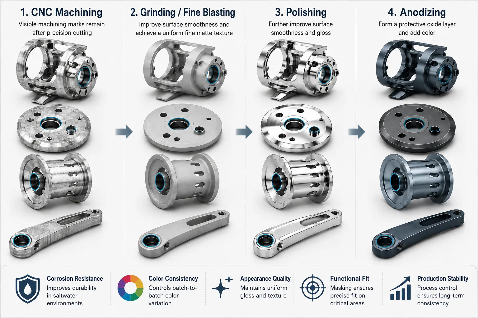
01|Why are fishing reel aluminum parts especially appearance-sensitive?
Many metal reel parts are structural and cosmetic at the same time. Frames and side plates define the visible product body, spools remain visible during operation, and handle-related parts are often decorative features.
One part can therefore contain:
- Class-A cosmetic surfaces;
- bearing bores;
- locating holes;
- threads;
- mating faces;
- rotating or assembly datums.
Treating every surface as one uniform anodizing requirement can create conflict: appearance passes but a fit changes, or a functional zone is protected while the masking boundary or rack mark becomes visually unacceptable.
02|Why does color variation begin before anodizing?
Different aluminum alloys, material conditions and upstream surface histories can respond differently after finishing.
| Upstream factor | Possible appearance effect |
|---|---|
| Alloy / material condition | Base tone and response after anodizing |
| Material lot | Small tone differences between lots |
| Blank or forming history | Surface and structural uniformity |
| CNC tool marks | May remain visible after anodizing |
| Local re-machining | Different reflection from surrounding areas |
| Repair or abnormal rework | High risk of visible mismatch |
For appearance-critical reel parts, production consistency improves when unnecessary variation in material source and upstream condition is reduced.
03|Why can CNC tool marks remain visible after anodizing?
Anodizing does not automatically level a machined surface.
Differences such as:
- toolpath direction;
- blend marks;
- chatter;
- worn-tool texture;
- hand-reworked areas;
can remain visible as differences in brightness, texture or reflection after surface treatment.
This is why a cosmetic machining requirement should not rely only on one roughness value. Two surfaces can have similar Ra values but very different tool-mark direction, continuity and local defects.
04|Polished, blasted or as-machined: how do they differ?
| Surface route | Typical visual direction | Main control point |
|---|---|---|
| Anodize after CNC | Retains machined character | Toolpath consistency and blend marks |
| Polish then anodize | Brighter, more reflective | Waves, over-polish and local bright spots |
| Blast / matte pretreatment | More uniform, lower reflection | Uniform texture, masking and edge consistency |
| Combined local finishes | Creates visual hierarchy | Boundary repeatability |
No single route is best for every reel.
The design intent should be defined first: visible precision-machined texture, bright metallic appearance or a low-reflection matte finish.
05|Why is maximum polish not always better?
Polishing controls texture, but it cannot solve every material or geometry issue.
Over-polishing can create:
- rounded edges;
- waviness on nominally flat surfaces;
- local geometry change;
- operator-to-operator reflection differences;
- a finish that is bright but not visually consistent after anodizing.
For reel cosmetic parts, the more useful target is often:
stable texture + stable geometry + repeatable anodized appearance
rather than maximum brightness.
06|Which surfaces should be managed separately from cosmetic areas?
| Functional zone | Main risk | What should be defined |
|---|---|---|
| Bearing bore | Coating changes fit | Masking and final dimensional state |
| Locating hole | Repeat location changes | Post-treatment size and datum |
| Thread | Assembly resistance changes | Whether coating is allowed |
| Mating face | Assembly attitude changes | Contact and coating requirement |
| Spool-shaft-related fit | Rotation can be affected | Final fit and runout condition |
| Cosmetic face | Color, scratches and texture | Color, gloss and limit sample |
Drawings and process documents are clearer when they distinguish:
Cosmetic Zone / Functional Zone / Masking Zone
instead of stating only “anodize entire part.”
07|Why can part geometry change perceived anodized color?
Fishing reel parts are rarely simple flat plates.
Deep recesses, cavities, thin edges, corners, holes and curved faces change surface preparation, rack conditions and the way light is reflected.
A local dark or light area should therefore not immediately be treated as a coloring defect. Investigation should also consider:
- upstream surface consistency;
- pretreatment consistency;
- geometry-related visual effects;
- rack location;
- local rework.
Appearance failure analysis should follow the entire process chain.
08|Why should rack points and masking be reviewed during DFM?
Anodizing requires reliable electrical contact and workholding, so rack contact cannot always be made invisible automatically.
If a rack point appears on a customer-facing Class-A surface, the part may fail cosmetically even when the color itself is acceptable.
During prototype DFM, define:
- Class-A visible surfaces;
- acceptable rack-contact areas;
- functional fits that require masking;
- whether masking boundaries may be visible;
- whether final assembly can hide process contact areas.
This is a shared design, CNC and surface-treatment decision.
09|How should appearance and color be inspected?
A robust appearance standard uses more than “looks close enough.”
| Inspection item | Control approach |
|---|---|
| Color | Approved color sample, limit samples or defined measurement method |
| Gloss | Controlled observation or specified instrument requirement |
| Texture | Approved reference part |
| Tool marks / polish | Defined direction and defect limits |
| Rack marks | Defined position and visibility limit |
| Scratch / dent | Cosmetic acceptance standard |
| Lot consistency | Retained samples and lot records |
Visual inspection should use consistent lighting, viewing angle and background because uncontrolled observation conditions create inspector-to-inspector disagreement.
10|Why does acceptable color not mean the surface treatment is fully acceptable?
Appearance is only one dimension of quality.
Depending on the product, final validation may need to consider:
coating condition + sealing + fit dimensions + appearance + assembly
A side plate can look excellent but have a bearing bore that is too tight after treatment. A spool can match the color target but still have a functional interface affected by the final coating state.
Final acceptance should therefore return to product function, not stop at color comparison.
11|Why does color drift from prototype to production?
Prototype
A few samples can be selectively polished, reworked or individually processed until the appearance is excellent. This does not prove production repeatability.
Pilot Production
Begin to freeze:
- material source and condition;
- CNC cosmetic machining method;
- polishing / blasting standard;
- rack and masking locations;
- surface-treatment route;
- inspection lighting;
- approved color and appearance limits.
Mass Production
Monitor:
- material lot variation;
- tool wear changing visible texture;
- polishing media and operator variation;
- blasting-media condition;
- surface-treatment lot variation;
- rack condition;
- reworked parts entering normal production;
- scratches introduced by handling and packaging.
Production success means repeated lots remain inside the same approved appearance window.
12|What should a cosmetic reel-part RFQ include?
| RFQ input | Why it matters |
|---|---|
| 2D drawing | Defines functional dimensions, masking and cosmetic zones |
| 3D model | Shows curves, recesses, rack options and visible areas |
| Material / condition | Supports anodizing and appearance risk review |
| Target color | Establishes the visual target |
| Surface texture | Defines CNC, polish, blast or combined route |
| A/B/C cosmetic zones | Sets inspection priority |
| Functional fits | Defines masking and final size requirements |
| Limit samples / color sample | Defines the acceptable appearance window |
| Quantity / annual volume | Supports lot control and retained-sample planning |
The earlier cosmetic and functional requirements are defined together, the lower the risk of a part that “looks right but does not fit” or “fits correctly but is visually rejected.”
FAQ
Why can anodized fishing reel aluminum parts show color variation even within one batch?
Final color is influenced by more than the anodizing bath. Alloy and material condition, CNC surface, polishing or blasting consistency, pretreatment, part geometry, coating and coloring conditions all affect appearance. The same nominal color can look different when the underlying surface condition is different.
Can bearing bores and locating holes be anodized together with cosmetic surfaces?
Not automatically. Whether anodic coating is allowed in bearing bores, locating holes, threads or mating surfaces depends on the final dimensional and assembly requirements. High-risk functional zones often need explicit masking, post-treatment dimensions or a defined finishing strategy.
Does a brighter polish always produce a better anodized fishing reel finish?
No. Polishing changes surface reflection and can also expose material or upstream machining differences. The goal should be a stable, repeatable texture rather than maximum brightness, and the polished condition should be qualified together with the target anodized color and approved appearance samples.
How should color consistency be controlled when reel cosmetic parts move from prototype to production?
Freeze the material source or condition, CNC and polishing or blasting standard, rack and masking plan, surface-treatment route, inspection lighting and approved limit samples. Production control should focus on keeping different lots inside the same acceptable appearance window.
