
In This Article
Direct Answer
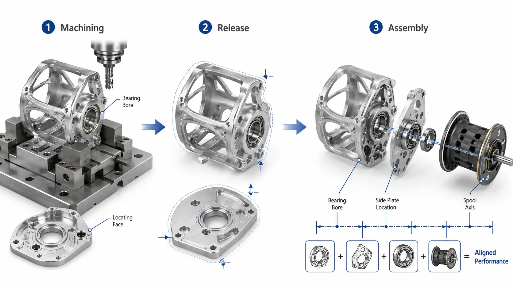
Fishing reel frames and side plates deform for more reasons than wall thickness alone. From blank preparation through roughing, finishing, unclamping, surface treatment and final assembly, the part repeatedly changes stress and constraint conditions. A dimension that is correct while the part is held in a CNC fixture may not remain correct after bearings, the spool and the side plate are assembled.
For reel performance, the control target is not one isolated bore. It is the functional dimension chain:
Frame bearing bores → side plate location → spool axis → gear axes → final assembly condition
01|Why are reel frames and side plates especially sensitive to distortion?
A reel frame can combine large material-removal areas, deep cavities, thin walls, bearing bores, threaded holes and cosmetic surfaces in one compact part. A side plate is often even thinner while also locating a bearing, brake structure or side mechanism.
As material is removed, structural rigidity falls, while the spatial relationship among bearing bores, locating features and mating faces still has to remain stable. The same drawing tolerance can therefore be much more difficult on a thin reel body than on a solid block.
Frame vs side plate: the risks are different
| Comparison | Frame | Side Plate |
|---|---|---|
| Main role | Establishes the main structure and axis datums | Supports bearings, locating features and side mechanisms |
| Typical geometry | Open structure, deep cavities, multiple interfaces | Thin shell or plate with local pockets |
| Main distortion risk | Overall twist and axis relationship shift | Warpage, local springback and repeatability loss |
| Critical interfaces | Bearing bores, gear shaft bores, datum faces | Bearing bore, locating holes, mating face |
| Assembly impact | Spool, gears and clutch | Spool, brake and repeated removal |
02|Distortion develops through the process
Thin-wall distortion is usually accumulated rather than created in one final step.
| Stage | What may change | What to control |
|---|---|---|
| Blank | Residual stress already exists | Material condition and stock allowance |
| Roughing | Heavy removal changes stress balance | Removal symmetry and allowance strategy |
| Semi-finishing | Lower wall thickness reduces rigidity | Support, clamping and datum stability |
| Finishing | Cutting force and local heat affect final geometry | Tooling, toolpath and sequence |
| Unclamping | Fixture constraint disappears | Free-state reinspection |
| Finishing / assembly | Fits and clamping state change again | Functional dimension verification |
This is why in-fixture accuracy is not the same as free-state accuracy.
03|Both under-clamping and over-clamping create risk
Insufficient clamping can cause vibration and part movement. Excessive clamping can be equally problematic on a thin-wall frame.
If the fixture pushes the frame out of shape before cutting, the machine removes material from a constrained geometry. The dimensions may look correct while clamped, but elastic recovery after release can shift bores, faces or profiles.
Fixture planning should therefore consider:
- whether functional datums are stable;
- whether support is placed near cutting-load areas;
- whether clamping direction bends a thin wall;
- whether roughing and finishing need different restraint strategies;
- whether critical CTQs are rechecked after unclamping.
04|The axis relationship matters more than one bore
The spool is a rotating system. Even when the bearing bore diameters in the frame and side plate are individually within tolerance, the final axis can still shift if the two support positions, side plate location or spool shaft do not align as a system.
A more functional chain is:
Frame bearing bore → bearing → spool shaft → side plate bearing bore → side plate location → final spool axis
For this reason, reel drawings need more than linear dimensions. Interfaces that control rotation and assembly may also require clear datums, position, coaxial relationship, perpendicularity, flatness or runout requirements.
05|Which CTQs matter most on frames and side plates?
| CTQ | Functional purpose | Possible symptom if unstable |
|---|---|---|
| Frame bearing bore relationship | Establish rotational support | Off-center spool, rubbing or noise |
| Gear shaft bore and related axis relationship | Maintain gear geometry | Rough feel or unstable mesh |
| Side plate locating holes | Repeat the installed position | Condition changes after removal |
| Side plate bearing bore | Establish the second rotational support | Spool axis shift |
| Mating-face flatness | Stabilize the side plate attitude | Local distortion after tightening |
| Critical hole position | Maintain mechanism geometry | Assembly shift or unstable action |
There is no universal tolerance value for every reel. Appropriate limits should be derived from the bearing, spool, gears, side plate and required assembly clearance as a complete stack.
06|Why staged machining often works better for demanding thin-wall parts
For a simple and rigid part, removing most material in one sequence can be efficient. A thin-wall reel frame must also manage stress redistribution and datum stability.
| Process approach | Machine close to final size in one sequence | Rough → semi-finish → finish |
|---|---|---|
| Material removal | Concentrated | Staged |
| Stress change | Harder to observe | Allows stabilization and recheck |
| Datum correction | Limited | Can be reconfirmed |
| Thin-wall formation | Earlier | Can be delayed |
| Better suited to | Simple, rigid geometry | Demanding thin-wall frames and side plates |
An extra operation does not automatically mean higher total cost. If it reduces sorting, rework and assembly matching later, it can support a more stable production process.
07|Why recheck after surface treatment?
Reel frames and side plates often combine cosmetic areas with functional fits. These two zones should not be controlled in exactly the same way.
For example:
- Bearing bores: define whether the finish is allowed inside the fit and where final size is specified;
- Locating holes: confirm whether the final locating condition changes after finishing;
- Mating faces: verify the datum and contact condition used in final assembly;
- Cosmetic surfaces: polishing, blasting and anodizing can change surface condition and visual consistency.
Critical fits are therefore better controlled with both machining-state and final-delivery-state requirements rather than a single inspection immediately after CNC machining.
08|Final verification should go beyond isolated part dimensions
For reel frames and side plates, CMM or dimensional inspection is only the first layer.
A more complete verification path is:
Part dimensions → critical interfaces → assembly → repeated assembly → functional condition
Questions may include whether spool rotation remains consistent after side plate removal and refitting, whether tightening creates new local distortion, or whether bearing installation changes rotational resistance. These effects can remain hidden when individual parts are inspected separately.
09|The control target changes from prototype to production
Prototype
Identify distortion locations, datum problems, fixturing risk and assembly interference.
Pilot Production
Freeze functional datums, fixtures, machining sequence, tooling and CTQ inspection methods, then confirm the reinspection condition after surface treatment and assembly.
Mass Production
The question is no longer whether one part can be made. The focus shifts to tool wear, fixture drift, blank variation and whether the same functional dimension chain can be maintained across batches.
10|What should be included in an RFQ?
| RFQ input | Why it matters for a frame / side plate |
|---|---|
| 2D drawing | Defines tolerances, datums, GD&T and CTQs |
| 3D model | Shows deep cavities, thin walls, tool access and fixture space |
| Material and condition | Affects machinability, stress and finishing route |
| Blank form | Influences stock allowance and datum planning |
| Surface treatment | Affects compensation, masking and final inspection state |
| Quantity / annual volume | Helps determine prototype or repeat-production fixture strategy |
| Assembly relationships | Builds the bearing, spool, gear and side plate tolerance chain |
| Critical functional requirements | Identifies which dimensions require CTQ control |
When a frame or side plate combines thin walls, bearing bores, cosmetic surfaces and assembly stacks, these requirements are best reviewed during prototype DFM rather than after finishing and assembly.
FAQ
Why can a fishing reel frame deform after CNC machining?
A reel frame often combines thin walls, deep cavities and multiple functional bores. Heavy material removal changes the original stress balance, while clamping and cutting load a low-rigidity structure. Once the part is released from the fixture, springback, twist or local dimensional change can appear.
Is bearing bore diameter the most important dimension on a reel frame and side plate?
No. Bore diameter is only one requirement. The geometric relationship among bearing bores, locating features, mating faces and rotational axes is often more important. A correct bore diameter alone does not guarantee spool alignment, gear mesh or repeatable side plate location.
Why can the spool still run off-center or feel tight when the frame and side plate pass inspection?
The final condition depends on the frame bearing bore, side plate bearing bore, locating features, spool shaft, bearings and clamping state working together. Individual tolerances can stack up after assembly and create axis shift, preload change or local interference.
Which process conditions should be fixed when moving a thin-wall reel frame from prototype to production?
The functional datums, fixturing method, machining sequence, tooling and critical parameters, CTQ inspection method, and post-finishing and post-assembly verification conditions should be fixed first so the same dimensional relationships can be reproduced across batches.
