
In This Article
Direct Answer
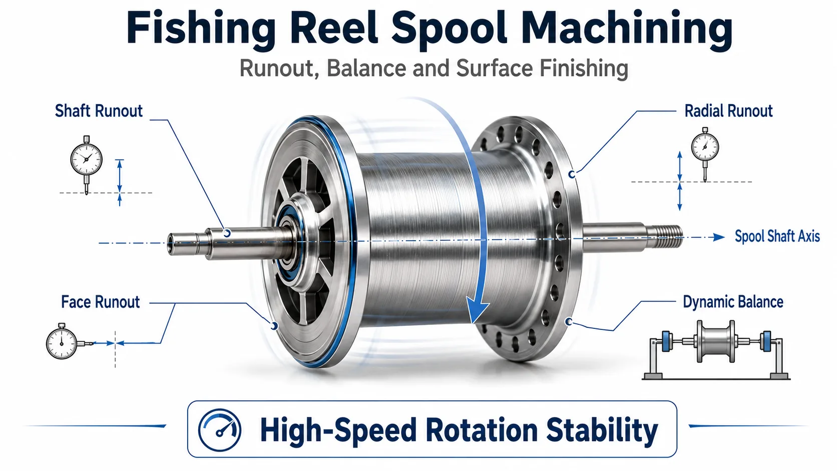
Fishing reel spool manufacturing is not difficult simply because the wall is thin. On baitcasting and conventional reels where the spool rotates at high speed, the manufacturing problem is the combined control of:
thin-wall rigidity + spool shaft + bearing support + radial runout + face runout + dynamic balance + brake structure + surface finishing
This means dimensionally in tolerance does not automatically mean low runout, balanced rotation, or a stable final assembly.
A spool can meet OD, width and bore dimensions and still vibrate, make noise, lose free-spin or change braking behavior if its rotation axis, mass distribution or assembled preload is unstable.
01|Why is a spool more than a thin cylindrical part?
A reel spool is often made light to reduce rotational inertia and improve response. The same weight reduction also lowers rigidity and makes the part more sensitive to fixturing and cutting loads.
| Design direction | Benefit | Manufacturing risk |
|---|---|---|
| Thinner wall | Lower weight and inertia | Lower rigidity and higher clamping sensitivity |
| Large cutouts | Further weight reduction | Greater sensitivity to local stiffness and mass distribution |
| Small shaft / bearing structure | Compact and lightweight | Greater sensitivity to shaft runout and preload |
| Cosmetic finish | Better appearance | Polishing, blasting, anodizing and dimensions become coupled |
For this reason, the spool should be planned as a high-speed rotating component rather than as a simple thin ring.
02|Four rotating errors matter more than one OD dimension
| Item | What it mainly describes | Possible symptom |
|---|---|---|
| Spool shaft runout | Stability of the shaft or shaft-related datum | Vibration or reduced free-spin |
| OD radial runout | Eccentricity of the OD relative to the rotation axis | High-speed vibration or noise |
| Face runout | Axial wobble of a rotating face | Axial instability or local interference |
| Dynamic balance | Distribution of mass around the axis | Increasing vibration as speed rises |
These measurements are not interchangeable.
A correct OD only confirms diameter size. It does not prove that the OD is centered on the rotation axis. Likewise, low geometric runout does not prove that material, pockets or brake features produce a balanced mass distribution.
03|Coaxial relationship, runout and dynamic balance are different
Coaxial relationship
Describes the relationship among the axes of cylindrical or rotational features.
Runout
Describes the periodic variation of a surface while the part rotates around a defined datum axis.
Dynamic balance
Describes the distribution of rotating mass, not simply geometric size.
A spool can be highly round but still show radial runout if the OD is eccentric to the spool shaft. Another spool can have low geometric runout but still vibrate at speed if local cutouts, wall thickness or brake features create uneven mass distribution.
The drawing and inspection plan should therefore identify whether a requirement is dimensional, geometric, runout-related or balance-related.
04|Why can thin-wall spools be distorted during fixturing?
Thin circular parts are sensitive to radial clamping force.
A common error chain is:
radial clamping → local ovalization → machining → unclamping → elastic recovery → change in bore / OD / face relationship
If the part is already distorted in the fixture, the machine cuts a constrained geometry. The part may inspect correctly while clamped and then change after release.
Process planning should therefore evaluate:
- soft jaws or purpose-built fixtures;
- support location near cutting loads;
- radial clamping that may ovalize the wall;
- stable axial location;
- separation of roughing and finishing when needed;
- free-state reinspection after release.
The target is not maximum clamping force. It is repeatable functional datums with minimum artificial distortion.
05|Why should the spool shaft define the rotating datum system?
The spool ultimately rotates about the bearing-supported axis. Critical rotating features should therefore be understood relative to the same functional axis:
spool shaft / bearing datum → spool OD → faces → brake cup or brake feature
If these features are created through unrelated datums in multiple setups, each re-location can add another error source.
This does not mean every design must be completed in one setup. It means every setup should preserve a traceable, repeatable functional datum relationship, with final runout or position verification used to confirm the result.
06|Why poor free-spin does not automatically mean bad bearings
Symptoms such as short free-spin, high-speed humming or a spool that becomes tight after the side plate is installed should not be assigned to one component immediately.
| Symptom | Possible manufacturing or assembly causes |
|---|---|
| Short free-spin | Spool shaft runout, bearing preload, misaligned supports, local rubbing |
| High-speed humming | Dynamic imbalance, OD runout, brake-cup runout, bearing condition |
| Rubbing at one angular position | Local radial runout, face wobble, side plate position shift |
| Tight after side plate installation | Bearing preload, shims, side plate bearing position |
| Normal again when side plate is removed | Assembly stack issue rather than spool body alone |
Diagnosis should therefore follow the complete rotating chain.
07|Why should the spool and brake system be considered together?
In baitcasting and conventional reels, the spool, shaft and brake-related rotating parts often share the same rotating system.
If a brake cup or related feature has:
- OD runout;
- uneven wall thickness or mass;
- eccentricity relative to the spool shaft;
- unstable location relative to the side plate;
the final symptom may appear as changing brake behavior, noise or inconsistent high-speed response rather than as obvious spool vibration.
Spool verification should therefore include its assembly relationship with the brake system and side plate support.
08|Why recheck function after surface finishing?
A spool is often both a high-speed rotating part and a cosmetic part.
Surface finishing therefore has to protect several different functions:
- Bearing or fit areas: define whether the coating is allowed in the fit;
- Shaft-related areas: preserve the final fit and datum condition;
- ODs and faces: recheck geometry when required;
- Cosmetic zones: control polishing, blasting, anodizing, color and texture;
- Masked areas: prevent functional dimensions from being changed by coating.
For a rotating part, confirming color alone is not enough. If final fits, runout or mass condition change after finishing, rotation can still be affected.
09|Spool inspection requires more than calipers
| Inspection item | Typical inspection approach |
|---|---|
| Spool shaft runout | V-block + dial indicator or dedicated runout fixture |
| OD radial runout | Runout tester or dial indicator |
| Face runout | Dial indicator |
| Bearing-fit dimensions | Precision bore / OD measurement |
| Critical geometric relationships | CMM or dedicated gauges |
| Dynamic balance | Balance verification when required by the product |
| Appearance | Controlled lighting, limit samples or cosmetic standard |
Inspection frequency should be based on CTQ risk and product requirements rather than a universal fixed percentage. First-piece, in-process, lot-based or high-frequency verification can then be assigned according to risk.
10|What tends to drift from prototype to mass production?
Prototype
Identify fixturing sensitivity, distortion locations, functional datums and whether a high-speed symptom comes from the spool itself or from the assembly chain.
Pilot Production
Freeze the fixture, clamping direction, machining sequence, tooling, runout inspection method, surface-treatment masking and final assembly verification method.
Mass Production
Watch for:
- tool wear shifting OD, pocket or face dimensions;
- fixture wear reducing rotating-datum repeatability;
- blank variation changing local wall thickness or mass distribution;
- finishing variation affecting fits and cosmetic appearance;
- bearing press fit, shims and side plate tightening changing assembly condition.
The production goal is not to make one exceptionally smooth spool. It is to reproduce the same critical rotational CTQs across batches.
11|What should be included in a spool RFQ?
| RFQ input | Why it matters |
|---|---|
| 2D drawing | Defines dimensions, GD&T, runout and fits |
| 3D model | Shows thin walls, cutouts, tool access and fixture space |
| Material and condition | Affects strength, machining and finishing route |
| Spool shaft structure | Defines the functional rotation datum |
| Bearing specification | Supports fit and bearing-system evaluation |
| Brake structure | Defines the brake cup or related rotating relationship |
| Surface treatment | Defines coating, masking and final dimensions |
| Balance requirement | Clarifies whether dedicated rotating verification is required |
| Quantity / annual volume | Guides fixture, inspection and production strategy |
Providing the assembly relationship among spool, bearings, side plate and brake structure helps identify the true CTQs earlier and reduces the risk of producing parts that meet isolated drawing dimensions but remain unstable in the finished reel.
FAQ
Why do fishing reel spools need both runout control and dynamic balance control?
Runout describes geometric deviation of the rotating shaft or surface relative to its datum axis, while dynamic balance describes how mass is distributed around the rotation axis. They are different problems: low geometric runout does not automatically mean balanced mass distribution, and both can affect vibration, noise and stability at speed.
Why can a spool vibrate at high speed even when its outside diameter is within tolerance?
Outside diameter only confirms the size of the diameter. It does not show whether the OD is eccentric to the rotation axis, whether the faces have runout, or whether mass distribution is balanced. High-speed behavior also depends on the spool shaft, bearing supports, radial runout, face runout and dynamic balance.
What should be rechecked after anodizing a fishing reel spool?
Depending on the drawing and functional requirements, recheck bearing-fit areas, locating or mounting surfaces, critical ODs and faces, spool-shaft-related dimensions, and any functional zone affected by the coating. For a high-speed rotating part, confirm that critical runout and the final assembly condition have not changed beyond the acceptable requirement.
Does short spool free-spin always mean the bearings are the problem?
No. Bearing condition is only one possibility. Spool shaft runout, bearing preload, alignment of the two bearing supports, side plate location, shim setting, local interference and brake-system condition can all increase rotational resistance, so the complete rotating dimension chain should be checked.
