
In This Article
Direct Answer
The smooth feel of a fishing reel is not a single gear parameter. It is the result of an assembled gear-mesh system.
A high-quality main gear can still feel rough if body shaft bores, shaft perpendicularity, pinion location, bearing seats, shims or axial preload move the gears away from the intended working geometry.
So:
gear accuracy in tolerance ≠ correct mesh geometry ≠ smooth assembled feel
A more functional chain is:
body datum → bearing seats → main shaft / pinion axis → gear mounting position → center distance → axial clearance → final mesh condition
01|Why should gear feel not be blamed on the gears alone?
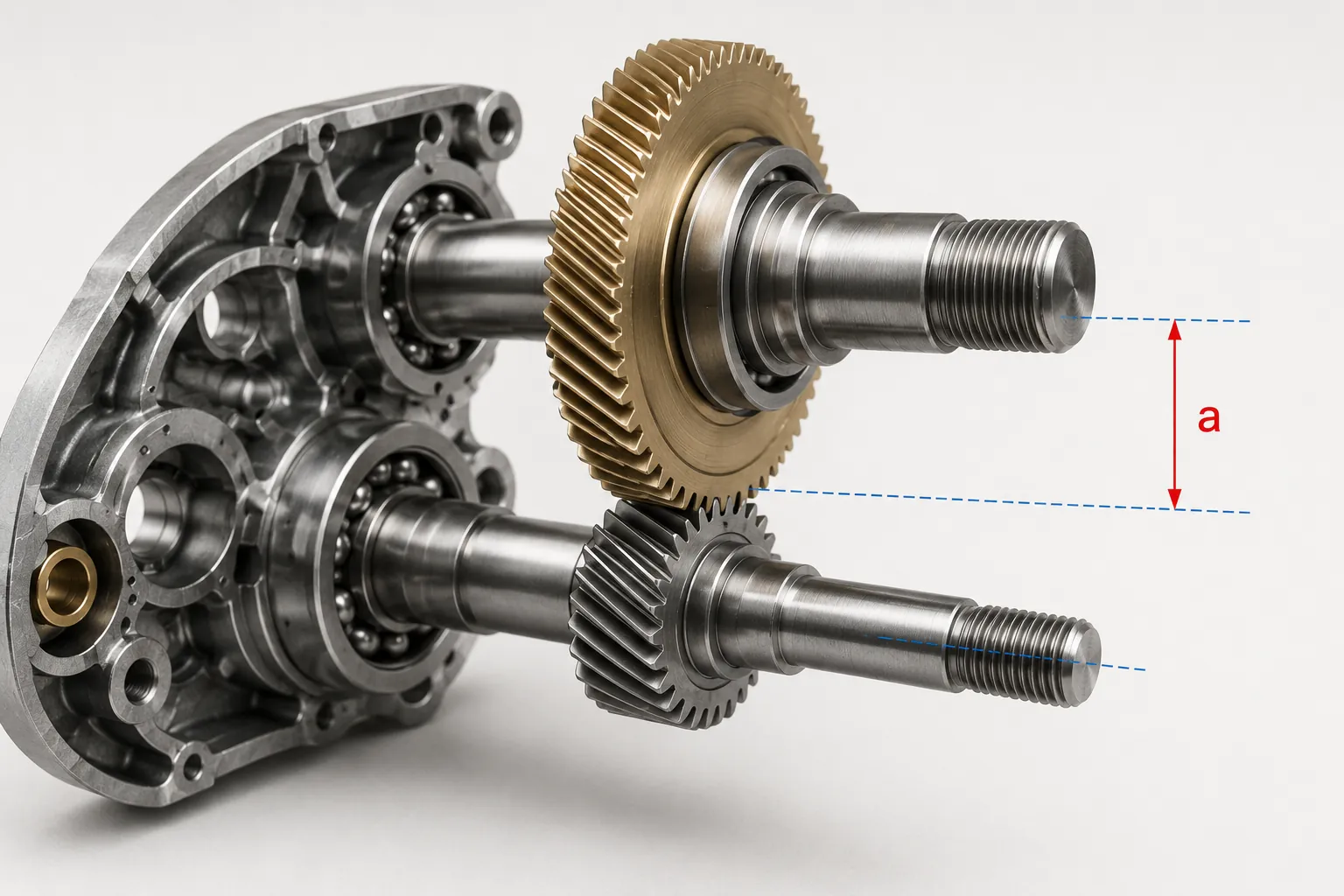
The main gear and pinion work inside a spatial relationship created by the reel body, shafts, bearings and side plate. Even when both gears pass individual inspection, installation geometry can change tooth contact and backlash.
| Influence | What it can change | Possible symptom |
|---|---|---|
| Main gear tooth geometry / surface | Contact quality | Grainy feel, noise |
| Main gear face runout | Periodic mesh position | Tight spot once per revolution |
| Pinion radial runout | Periodic mesh center | Cyclic noise |
| Shaft center distance | Backlash and mesh depth | Tight feel or excess play |
| Main shaft perpendicularity | Contact alignment | Uneven contact, changing resistance |
| Bearing clearance / preload | Actual working axis | Variation in feel |
| Shims | Axial gear position | Tightness, looseness or play |
| Burrs / debris | Local contact | Intermittent catch or roughness |
A rough feel should therefore not automatically trigger tighter gear tolerances without checking the supporting geometry.
02|What is the functional tolerance chain behind gear mesh?
A simplified reel gear-mesh chain is:
body functional datum → main gear bearing seat / shaft → pinion bearing seat / axis → shaft center distance → axial gear location → final tooth contact
Every node can contribute variation.
Center distance on a drawing is not merely the mathematical distance between two isolated hole centers. In service it is created by real bearing fits, shaft attitude and assembled geometry.
A shaft bore can be correctly positioned while its axis is tilted, and the resulting tooth contact can still become uneven.
03|How does center distance change reel feel?
| Center-distance condition | Possible mesh change | Possible result |
|---|---|---|
| Too small | Deeper contact and greater interference risk | Tight rotation, increased resistance |
| Within design window | Intended contact and clearance | Stable rotation and more uniform sound |
| Too large | Shallower contact and larger clearance | Backlash, knocking feel, noise |
Center distance cannot be judged independently of the gear design. Tooth geometry, axial installation, bearing clearance and body deformation all affect the working condition.
The goal is not one universal center-distance number, but a repeatable mesh window for the specific design.
04|What do position, perpendicularity, coaxial relationship and runout control?
Shaft-bore position
Controls where the main or pinion axis sits in the body and contributes directly to center distance.
Shaft-axis perpendicularity
Controls whether the shaft stands at the correct attitude relative to its mounting datum. Correct center location does not guarantee a straight working axis.
Coaxial relationship
Controls multiple bores, bearing seats or shaft sections intended to share one rotational axis.
Runout
Shows periodic variation of a gear or shaft feature as it rotates about the datum axis.
The drawing should first define the functional datum structure, then apply the GD&T that corresponds to the actual failure mode rather than simply tightening every dimension.
05|Why do bearing seats change the real gear center distance?
A bearing seat is more than a hole that accepts a bearing.
The working shaft axis is affected by:
- bearing-seat diameter and roundness;
- alignment between support locations;
- bearing-to-seat fit;
- bearing internal clearance or preload;
- shaft straightness and runout;
- geometry after the body or side plate is tightened.
If a tight fit distorts the support or two bearing locations do not share the intended axis, the real working axis can move away from the theoretical drawing axis.
Bearing-seat inspection should therefore support shaft-axis stability, not just report one diameter value.
06|Which CTQs matter most for the main gear and pinion?
| Part / interface | Key CTQ | Main effect |
|---|---|---|
| Main gear | Tooth geometry, face runout, mounting face, bore relationship | Feel, cyclic resistance, noise |
| Pinion | Tooth radial runout, coaxial relationship, end face, burrs | Mesh, clutch movement, noise |
| Main shaft | Straightness, perpendicularity, axial location | Main gear attitude |
| Body bearing seats | Diameter, position, axis relationship | Center distance and shaft stability |
| Side plate support | Repeat location, bearing position | Axis change after assembly |
| Shims | Thickness, combination, orientation | Axial clearance and preload |
The correct CTQ is not simply the dimension with the smallest tolerance. It is the characteristic whose variation directly reaches gear mesh and user feel.
07|Why can shims not replace geometric accuracy?
Shims can typically adjust:
- axial clearance;
- bearing or gear axial position;
- preload;
- assembly variation within the intended design range.
They cannot correct:
- incorrect shaft center distance;
- shaft-bore position error;
- poor shaft perpendicularity;
- gear face or radial runout;
- misaligned bearing seats;
- burrs on tooth or pinion functional surfaces.
If mass-production reels require skilled technicians to repeatedly try different shim combinations to achieve consistent feel, the tolerance chain and CTQs should be reviewed instead of using selective shimming as a permanent correction method.
08|Why can a small burr become a gear-feel problem?
Many surfaces in a reel gear system rotate, slide or mesh repeatedly.
A small burr on a pinion end face, bore entrance, tooth edge, shaft shoulder or nearby functional edge may not cause a basic size failure, but can still create:
- rough pinion sliding;
- incomplete clutch disengagement or return;
- local mesh disturbance;
- an intermittent tight spot;
- scratches during shaft or bearing assembly.
Deburring should therefore be based on functional zones, and must remove the burr without changing tooth geometry, functional length, fit or edge location.
09|How should dimensional inspection connect to mesh verification?
Part inspection alone does not prove the final mesh.
A stronger verification chain is:
part dimensions → shaft-bore / axis geometry → gear runout → assembled axial clearance → mesh condition → rotational torque / feel / sound
| Verification object | Typical method |
|---|---|
| Shaft-hole position and axis geometry | CMM / dedicated gauge |
| Bearing-seat dimensions | Precision bore measurement |
| Main gear face runout | Dial indicator / runout inspection |
| Pinion radial runout | Runout or gear inspection |
| Shim thickness | Precision thickness measurement |
| Assembled axial clearance | Displacement, gauge or dedicated method |
| Final mesh | Rotational torque, defined feel, sound or functional test |
The inspection method should follow the drawing, tolerance and product requirement rather than applying one instrument to every part.
10|Why does smoothness drift from prototype to mass production?
Prototype
Engineers can often use selective assembly, shims and manual adjustment to make a small number of prototypes feel excellent. This can hide an unstable tolerance chain.
Pilot Production
The process should begin to freeze:
- functional datums;
- shaft-bore machining and inspection;
- gear assembly orientation;
- shim matrix;
- deburring standard;
- lubrication location and quantity;
- mesh verification method.
Mass Production
Key variation sources include:
- tool wear shifting shaft-hole dimensions or position;
- fixture repeatability drift;
- batch variation in gear runout and tooth surfaces;
- bearing fit and clearance variation;
- shim mix-up or thickness variation;
- burr and cleanliness variation;
- assembly effects on preload and axial location.
Stable production means different operators and batches remain inside the same process window without depending on a few experienced technicians to tune every reel.
11|What should be included in a gear and shaft RFQ?
| RFQ input | Why it matters |
|---|---|
| 2D drawings | Define gears, shaft bores, datums, GD&T and runout |
| 3D model | Shows body, bearing-seat and gear spatial relationships |
| Gear data | Defines the intended mesh and center-distance window |
| Shaft and bearing specifications | Establish real support and fit conditions |
| Datum scheme | Defines how position, perpendicularity and runout are measured |
| Shim / axial-clearance requirement | Defines assembly adjustment strategy |
| Burr and edge requirements | Identifies sliding, mesh and assembly risk zones |
| Lubrication and assembly requirement | Defines final verification condition |
| Quantity / annual volume | Supports fixture, gauge and process-control planning |
When every individual part passes inspection but assembled feel remains inconsistent, the related parts should be reviewed as one gear-mesh tolerance chain during RFQ and DFM rather than simply tightening one gear tolerance.
FAQ
Why can a fishing reel still feel grainy when the gears pass inspection?
Gear accuracy is only one part of the mesh system. Main gear face runout, pinion radial runout, shaft center distance, shaft perpendicularity, bearing clearance, shims and lubrication can all change the real contact condition, so acceptable individual gears do not guarantee a smooth assembled reel.
What happens when fishing reel gear center distance is too large or too small?
A center distance that is too small can make the mesh tight, increase rotational resistance and create abnormal local contact. A distance that is too large can increase backlash, noise and mesh instability. The acceptable range must be derived from the actual gear geometry, bearing support, axial location and assembly clearance.
Can shims solve every fishing reel gear mesh problem?
No. Shims are mainly used to adjust axial position, preload or assembly clearance. If the root cause is shaft-hole position, center distance, shaft perpendicularity, gear runout or burrs, changing shims can alter the symptom but cannot correct the underlying geometric datum error.
Which CTQs matter most when a fishing reel gear system moves from prototype to production?
Priority CTQs include the positions of the main-gear and pinion shaft bores, center distance, shaft perpendicularity, gear radial and face runout, bearing-seat dimensions and fits, critical axial clearance and burr condition. Final assembled mesh, torque or defined feel verification should confirm the tolerance chain.
