
In This Article
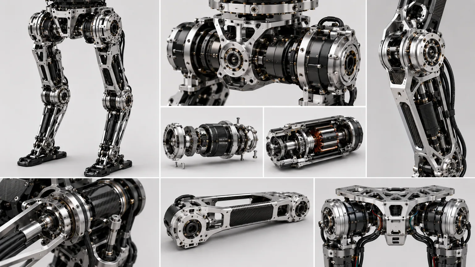
Direct Answer
The hip and knee determine whether a humanoid can:
- stand and balance on one leg;
- walk, reverse, side-step and turn;
- squat, rise and carry;
- climb steps and cross obstacles;
- walk quickly, run and jump;
- recover from external disturbance;
- protect itself in a fall and stand up.
The manufacturing chain is:
Pelvis interface → three-axis hip → thigh load path → knee → calf interface → ankle and foot → ground contact → gait
| Module | Function | Manufacturing focus |
|---|---|---|
| Hip | Pitch, roll and yaw | Axis geometry, torque, backlash and harness |
| Thigh frame | Connect hip and knee | Low mass, stiffness, length and load path |
| Knee | Flexion, cushioning and propulsion | Axis, support, brake and impact resistance |
| High-torque actuator | Motion and pose holding | Motor, reducer, bearing, sensing and thermal |
| Calf/ankle interface | Transfer ground reaction | Datum, length and bilateral consistency |
| Gait calibration | Map joints to real foot pose | Zero, axes, length, backlash and elasticity |
1. Why Hip and Knee Production Is Difficult
The hip and knee repeatedly support whole-body mass and ground reaction. Required cases include gravity holding, single-support balance, high-speed leg swing, squat torque, landing impact, running power and fall recovery.
Separate:
- continuous torque;
- peak motion torque;
- impact survival moment;
- allowable lost motion and elastic deflection;
- thermal derating;
- target life and maintenance interval.
Maximum motor torque alone does not prove production suitability.
2. Why the Hip Normally Uses Three Degrees of Freedom
Hip directions are:
- pitch: forward and backward leg swing;
- roll: lateral movement and single-leg balance;
- yaw: leg rotation and turning.
| Architecture | Advantage | Risk |
|---|---|---|
| Three serial single-axis modules | Modular and easy to model | Height, inertia and accumulated error |
| Near-intersecting axes | Ball-joint-like kinematics | Difficult packaging and assembly |
| Offset axes | Easier motor/reducer packaging | More complex model and interference |
| Differential/coupled | Compact and power dense | Decoupling, backlash and calibration |
| Tendon/remote drive | Lower local leg mass | Friction, stretch and pretension |
| Parallel spherical | Directional stiffness optimization | Part count and service complexity |
Pitch, roll and yaw loads differ. Component commonality should not force identical ratios and supports across all axes.
3. Knee Architecture: Fixed Axis or Moving Center
Most production humanoids use a fixed-axis knee because it offers fewer parts, clear modeling, simpler bearing support, lower accumulated backlash and easier service.
A four-bar or moving-center knee may improve folding, torque leverage, exterior packaging and human-like geometry. It also adds link-center tolerance chains, additional bearings, friction, closed-chain internal force and multi-pose calibration.
A fixed axis usually wins when reliability and cost dominate. A moving-center design is justified only when deep folding, close-body packaging or a specific torque curve brings measurable task value.
4. Public Technology Comparison
This comparison uses publicly confirmed information available through August 2026. Undisclosed gear geometry, bearing preload and tolerance chains should not be inferred from videos.
| Platform | Publicly confirmed focus | Manufacturing lesson |
|---|---|---|
| Tesla Optimus | Bespoke motors, geartrains, actuator integration, validation and manufacturing tests | Co-develop motor, gear, bearing, electronics, thermal and production equipment |
| Unitree H1/G1 | High-torque joints, crossed-roller bearings, internal-rotor PMSMs, dual encoders and hollow routing | Standardized modules across robot sizes and price points |
| Honda ASIMO | Ground-reaction, model-ZMP and foot-placement control, long-term operation and safety | Millions of cycles and fall safety matter beyond peak performance |
| Boston Dynamics Atlas | Repeated subassemblies, identical limbs and no cables across joints | Reduce harness failures, increase commonality and service speed |
A production robot can combine all four principles.
5. Tesla Optimus: Bespoke Actuators and Manufacturing Integration
Tesla has not published complete current hip/knee torque, reducer sections or bearing arrangements. Its official teams and roles do confirm development of bespoke motors, geartrains, actuator integration, mechanical and thermal validation, and gearbox assembly/test processes for large-scale automation.
The lesson is to freeze these together:
| Area | Required decisions |
|---|---|
| Motor | Torque constant, speed, inertia, heat and insulation |
| Geartrain | Ratio, lost motion, efficiency, lubrication and life |
| Output support | Bearing type, span and overturning moment |
| Sensors | Motor-side, output-side, torque and temperature |
| Brake | Power-off holding, release and thermal behavior |
| Housing | Datums, stiffness, cooling and sealing |
| Electronics | Power stage, connector and harness |
| Production | Pressing, preload, torque, test and traceability |
The key is synchronized actuator, validation and manufacturing-equipment development.
6. Unitree H1 and G1: High Torque Density and Modular Joints
Unitree publishes clearer specifications.
H1 / H1-2
- three hip DoF and one knee DoF per leg on H1;
- industrial crossed-roller output bearings;
- low-inertia high-speed internal-rotor PMSMs;
- published ultimate torque of about 360 N·m at the knee and 220 N·m at the hip;
- approximately 400 mm thigh and 400 mm calf;
- additional ankle freedom on H1-2.
G1
- six DoF per leg;
- published maximum knee torque of about 90 N·m or 120 N·m by version;
- crossed-roller output bearings;
- low-inertia internal-rotor PMSMs;
- dual encoders;
- full-joint hollow routing;
- local air cooling;
- combined thigh and calf length of about 0.6 m.
H1 and G1 are not simple scale copies. H1 prioritizes full-size motion output; G1 reduces torque and size for cost, compactness and developer accessibility.
Published ultimate torque is not continuous torque and cannot be copied into another robot specification.
7. Honda ASIMO: From Gait Control to Tens of Millions of Steps
Honda reports that all ASIMO units accumulated more than 33.26 million steps and about 7,907 km of walking. Long-term operation shifted attention toward shared-space stability, disturbance recovery, fall risk, repeated reliability and maintenance.
Honda research summarizes stabilization through:
- ground reaction force control;
- model ZMP control;
- foot landing position control;
- uneven and sloped floor adaptation;
- limiting slip and spin during running.
Manufacturing must reproduce the small corrections demanded by these controls.
| Control behavior | Manufacturing requirement |
|---|---|
| Ground-reaction correction | Low and repeatable hip/knee friction |
| ZMP adjustment | Bilateral axis, length and zero consistency |
| Foot-placement correction | Accurate effective thigh/calf length |
| Uneven floor adaptation | Predictable hysteresis |
| Long-term walking | Bearing, reducer, brake and harness life |
| Human safety | Fall, collision, cover and power-loss validation |
One dynamic demonstration does not replace long-cycle reliability.
8. Boston Dynamics Atlas: Commonality, Symmetry and No Cross-Joint Cables
Boston Dynamics describes the electric Atlas as task-efficient rather than limited by human joint ranges.
Its 2026 product approach includes:
- repeating subassemblies;
- identical left and right arms;
- identical left and right legs;
- repeated shoulder and pelvis structures;
- infinite actuator rotation;
- elimination of cables across joints.
Traditional cross-joint harnesses limit angle and create fatigue, rubbing, connector and sensor-force problems. Atlas publicly confirms the design objective but not all internal electrical details.
Identical legs reduce part count, assembly errors, fixtures, spares and service time. Full symmetry may reduce local optimization, so commonality and performance must still be balanced.
9. Engineering Principles from the Four Routes
| Principle | Meaning |
|---|---|
| Do not copy one robot | Public information and missions differ |
| Size torque by axis | Hip pitch, roll, yaw and knee loads differ |
| Separate ultimate and continuous | Peak torque does not define thermal life |
| Design the actuator as a system | Motor, reducer, bearing, brake, sensing and housing |
| Use commonality carefully | Common joints can add unnecessary distal mass |
| Treat harness as mechanics | Routing and twist life must be designed early |
| Validate accumulated steps | Peak motion is not commercial reliability |
| Calibrate the whole leg | Passing part dimensions does not prove foot accuracy |
10. Hip Machining CTQs
| CTQ | Failure effect | Control |
|---|---|---|
| Pelvis interface | Bilateral pose and load input error | Common datum, face and pilot |
| Three-axis direction | Real kinematics differs from model | Multi-pose CMM identification |
| Axis intersection/offset | Foot path and interference change | Combined fixture and calibration |
| Bearing-seat coaxiality | Friction, heat and life loss | Single setup or assembly measurement |
| Reducer pilot | Eccentric load and noise | Pilot, face and runout |
| Output flange | Thigh pose error | Face, locating and bolt circle |
| Sensor mounting face | Zero drift and cross-coupling | Flatness, preload and thermal check |
| Mechanical stop | Overtravel and internal impact | Angle, strength and cushioning |
Final assembly must be measured as a multi-axis system.
11. Knee Machining CTQs
| CTQ | Failure effect | Control |
|---|---|---|
| Knee axis to thigh datum | Leg-length and foot-path error | CMM and combined datum |
| Bearing-seat coaxiality | Binding, heat and wear | Combined finishing |
| Bearing span | Low overturning stiffness | Load and assembly check |
| Output flange face | Calf installation tilt | Face and perpendicularity |
| Axial play | Foot wobble and impact noise | Preload, shims and play test |
| Brake interface | Power-off drop or drag | Gap, torque and response |
| Stop structure | Overload in squat or fall | Strength and cushioning |
| Encoder zero | Bilateral pose mismatch | Mechanical reference and auto calibration |
Stiffness near full extension is especially important because small knee-angle error changes robot height and center of mass.
12. High-Torque Actuator System
Typical content:
- PMSM;
- harmonic, planetary, cycloidal or other reduction;
- output bearing;
- motor and output encoders;
- torque sensing;
- brake;
- power electronics and thermal sensing;
- housing, sealing and cooling.
Peak torque, ratio and bearing static rating are insufficient. Continuous output, backdrivability, impact, thermal state, lubrication and service must be evaluated.
13. Bearings, Reducers and Housing Validation
Hip/knee outputs carry radial, axial, overturning, torque, impact and vibration loads.
Crossed-roller bearing performance depends on seat roundness, coaxiality, face parallelism, preload, local housing stiffness, tightening sequence and temperature.
Test:
- no-load rotational resistance;
- axial and radial play;
- angular deflection under known moment;
- forward/reverse lost motion;
- temperature rise;
- post-impact remeasurement;
- life wear and zero change.
14. Lightweight Thigh Frame
Routes include CNC aluminum, forged/cast blanks with finish machining, magnesium, CFRP tubes with metal ends, topology-optimized metal and separate structural frames/covers.
A thigh must reduce swing inertia while sustaining bending, torsion and landing impact.
Validate not only static FEA, but impact, side load, joint-face microslip, machining distortion and gait fatigue.
15. Harness, Brake and Cooling
Define hollow-routing diameter, power/encoder/brake/data separation, fixed and moving ends, neutral length, bend radius, accumulated twist, edge clearance, strain relief, cooling path and module removal sequence.
Dual encoders, brakes and high-current motors increase routing density. Routing cannot be postponed until after housing design.
16. Impact, Thermal and Accumulated-Step Validation
Validate:
- single extreme events such as impact, emergency stop, deep squat and power loss;
- action cycles such as walking, running, stairs, carrying and turning;
- long life including accumulated steps, bearing/reducer wear, harness fatigue, brake wear, lubrication, fastener loosening and encoder drift.
Honda’s experience demonstrates why millions of repeatable cycles are closer to commercial value than one spectacular motion.
17. Full-Leg and Gait Calibration
The chain is:
Motor encoder → reducer output → real hip axes → knee axis → effective link lengths → ankle/foot pose → ground contact
Calibrate pelvis datums, hip axes, knee zero, link lengths, foot interface, backlash, loaded elasticity, thermal/harness effects, bilateral consistency and foot-force coordinates.
Whole-robot calibration then aligns standing height, pelvis pose, center of mass and gait compensation.
18. End-of-Line Production Testing
Recommended tests:
- phase resistance and back-EMF;
- encoder zero and scale;
- no-load friction;
- torque-speed curve;
- lost motion and stiffness;
- brake hold and release;
- thermal rise;
- vibration and noise;
- harness communication;
- full-leg foot accuracy;
- serialized data linkage.
Testing should generate actuator and leg parameters, not only pass/fail labels.
19. Prototype-to-Production Route
- 01Define Motion and LoadsWalk, run, squat, carry, impact and recovery.
- 02Select ArchitectureSerial, intersecting, offset, coupled and fixed- or moving-center knee.
- 03Co-design ActuatorsMotor, reducer, bearing, brake, sensing and thermal.
- 04Engineering PrototypeFrame, axes, harness, stops and assembly fixtures.
- 05Full-Leg CalibrationZero, axes, lengths, backlash, elasticity and foot pose.
- 06Impact and LifeLanding, thermal, accumulated steps, harness and brake.
- 07Freeze ProductionCTQs, automated tests, traceability and repair.
20. Information Required for RFQ and Engineering Review
| Category | Recommended information |
|---|---|
| Robot | Height, mass, pelvis width and center of mass |
| Motion | Hip/knee DoF, range, speed and gait |
| Loads | Continuous, peak, landing, carrying and fall |
| Transmission | Motor, reducer, bearing, brake and sensors |
| Interfaces | Pelvis, thigh, knee, calf, ankle and foot |
| Material/finish | Frame, shafts, bearing seats, fasteners and lubrication |
| Harness/thermal | Power, encoder, brake, data and cooling |
| Mass target | Joint, thigh, calf mass and inertia |
| Calibration | Axes, zero, link lengths, foot and force sensing |
| Validation | Lost motion, stiffness, thermal, impact and accumulated steps |
| Traceability | Parts, torque, preload, curves and software |
Frequently Asked Questions
Why do humanoid hips normally need three degrees of freedom?
The hip must provide forward-backward swing, lateral motion and internal-external leg rotation, corresponding to pitch, roll and yaw. Three degrees of freedom support walking, turning, side-stepping, single-leg balance and fall recovery, but increase axis, harness, mass and calibration complexity.
Can the published 360 N·m knee torque of Unitree H1 be used directly as a design target for another robot?
No. The published 360 N·m is the ultimate torque of a specific H1 joint unit. Another robot must recalculate requirements from total mass, thigh and calf length, speed, landing impact, ratio, thermal condition and life.
Is a single-axis knee or a four-bar knee better?
A single-axis knee has fewer parts, clear kinematics and simpler calibration and service, making it suitable for production reliability. A four-bar or moving-center knee can improve folding and human-like motion but adds tolerance chains, friction, backlash and assembly calibration.
Why can gait remain unstable when all hip and knee parts pass dimensional inspection?
Gait also depends on bearing preload, reducer lost motion, frame elasticity, encoder zero, bilateral leg-length difference, foot installation, harness reaction, temperature and control parameters. Full-leg and whole-robot calibration are required.
