
In This Article
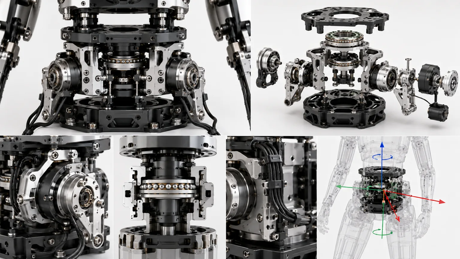
Direct Answer
The waist and torso sit at the center of humanoid mass and load transfer. Above are the arms, head, computing hardware and batteries; below are the pelvis and legs. Waist design affects:
- arm and hand workspace;
- center-of-mass motion during walking and turning;
- bending and torsional resistance during carrying;
- squatting, rising and fall recovery;
- upper-body inertia and energy use;
- cable, cooling and electronics packaging;
- maintenance and module replacement.
The manufacturing chain is:
Joint axes → load path → transmission stiffness → sensors → harness → torso pose
| Module | Main function | Manufacturing focus |
|---|---|---|
| Pelvis interface | Connect legs and waist | Datums, stiffness and load input |
| Waist joints | Pitch, roll and yaw | Axis geometry, backlash and stops |
| Torso frame | Carry arms, head and equipment | Low mass, bending/torsional stiffness |
| Transmission | Motors, reducers, belts or tendons | Torque, stiffness, friction and service |
| Sensor interface | Position, torque, attitude and temperature | Mounting, zero and stability |
| Harness and cooling | Power, data and thermal management | Bend, twist, fixing and access |
1. Why the Waist Changes Whole-Robot Capability
Without an articulated waist, turning, reaching and carrying depend more heavily on hips, footsteps and shoulders. A waist can:
- extend arm workspace;
- turn the upper body without moving the feet;
- shift the center of mass during gait;
- avoid shoulder-limit postures;
- support squatting and fall recovery;
- counteract whole-body disturbance.
DLR upper-body robots use torso motion to expand arm and hand workspace and use link-side torque sensing for sensitive manipulation. Other full-size humanoids use only one torso axis, confirming that there is no universal DoF count.
2. Select Two-Axis, Three-Axis or Flexible Torso from the Task
| Architecture | Capability | Advantage | Main risk |
|---|---|---|---|
| Pitch + yaw | Bending and horizontal turning | Direct, lighter and simpler | No active roll |
| Pitch + roll + yaw | Main human-like waist motions | Strong balance and task range | More structure, harness and calibration |
| Serial orthogonal joints | Stacked one-axis modules | Clear modeling and modularity | Height, inertia and accumulated error |
| Spherical / parallel joint | Concentrated multi-axis center | Compact and stiff in selected directions | Complex machining and kinematics |
| Coupled tendon waist | Remote actuators and coordinated motion | Low mass and compliance | Friction, pretension, coupling and service |
| Segmented robotic spine | Large motion from small segment angles | Human-like shape and compliance | Part count and reliability |
A three-motor three-DoF coupled tendon study showed that yaw, pitch and roll require different balancing moments, so tendon routing and mechanical advantage should not be copied across axes. Research prototype values are not universal commercial specifications; each robot needs its own mass, payload, speed and recovery analysis.
3. Derive Joint Requirements from Whole-Body Motion
Typical simulation cases include:
- standing with both arms extended;
- one- and two-arm carrying;
- upper-body turning;
- bending to pick an object;
- squat and rise;
- stepping and obstacle crossing;
- fall protection and self-recovery;
- single-support disturbance;
- external push or collaborative load.
Required outputs include:
- angle range;
- peak and continuous torque;
- speed and acceleration;
- bearing radial, axial and overturning load;
- torso deflection;
- center-of-mass trajectory;
- power and temperature;
- harness space at extreme pose.
The HRP-2 development process defined cooperative carrying, uneven-ground walking, fall and recovery tasks first, then used motion simulation to set joint ranges, outputs and speeds.
4. Heavy-Object Handling Starts Before the Object Is Lifted
Waist value is not defined only by maximum angle and torque. The robot must also create an effective preparation posture before the load is moved.
A human-motion study of shelf handling used optical motion capture, shoe-mounted six-axis force/torque sensors and ZMP evaluation. Nine male subjects aged 21–24 handled 0 kg, 5 kg and 10 kg loads. Two torso behaviors were observed:
- The torso leaned slightly backward before lifting;
- During placement, the torso moved closer to the object, reducing wrist-to-shoulder distance and arm demand.
Heavier loads produced earlier preparation and more pronounced torso adjustment during placement.
The subject group and test environment were limited, so the measured timing and angles should not be copied as universal robot thresholds. The engineering lesson is that waist validation must include dynamic coordination before and after the nominal task pose.
| Human behavior | Robot engineering requirement |
|---|---|
| Slight backward preparation before lift | Pitch range and speed must support preloading posture |
| Earlier preparation for heavier objects | Motion timing should respond to estimated payload |
| Torso approaches the object during placement | Waist and footsteps should shorten the arm moment arm |
| Whole-body balance is maintained | Torso pose should coordinate with foot force, ZMP or CoM state |
| Small posture changes are useful | Backlash, friction and zero error must not hide small motions |
| Behavior depends on shoulder–wrist distance | Calibration must link waist angle, shoulder location and hand workspace |
Engineering prototypes should add:
- Payload-graded motion tests: compare timing and posture at no load, light load and rated load;
- Arm-load evaluation: record shoulder torque, hand distance and waist pose together;
- Whole-body coordinate calibration: align waist encoders, IMUs, foot force/torque sensing and hand payload.
A waist may have sufficient nominal range but still fail to reduce arm load if backlash, low stiffness or harness reaction prevents stable small-angle postures.
5. The Load Path Defines the Torso Frame
A typical path is:
Arms and head → shoulder crossmember / chest frame → waist → pelvis → hips and legs → ground
The waist carries:
- upper-body gravity moment;
- overturning moment from extended arms;
- continuous carrying load;
- inertial torque during fast turning;
- gait impact and ground-reaction transfer;
- transient fall and recovery load.
| Weak area | Typical consequence |
|---|---|
| Flexible shoulder crossmember | Moving arm datums and hand error |
| Thin torso side plates | Twist and sensor-zero change |
| Flexible waist flange | Upper-body oscillation |
| Small bearing span | Low overturning stiffness |
| Weak pelvis interface | Loosening and fatigue |
| Offset equipment mass | Bilateral imbalance |
Lightweighting should use closed sections, ribs, bearing span and clear load-entry points rather than simply removing material.
6. Converting Running-Landing Loads into Waist and Pelvis Requirements
A pelvis mechanism developed for a biped running robot provides a useful design principle: waist and pelvis requirements should be derived from human motion, ground reaction and landing impact, not static gravity alone.
The research targeted human-like mass properties and link dimensions. Its reference model represented a person about 1500 mm tall and 60 kg, used an approximately 170 mm hip spacing and required the mechanism to tolerate roughly 2000 N landing impact. Human running ground reaction, joint-angle data and a SLIP model were used to derive axis requirements.
The following values belong only to that research prototype, but they show that the three directions had very different demands:
| Prototype axis | Range | Motor torque | Target speed | Toughness moment |
|---|---|---|---|---|
| Pelvis roll | -14° to +14° | 44 N·m | 2.3 rad/s | 231 N·m |
| Hip roll | -26° to +26° | 113 N·m | 0.8 rad/s | 160 N·m |
| Hip yaw | -70° to +20° | 29 N·m | 1.2 rad/s | 29 N·m |
Two quantities must be separated:
- Actuation torque: continuous or peak output required for commanded motion;
- Toughness moment: external moment that the reducer, bearings, shafts and frame must survive during landing or abnormal loading.
Meeting motor-output demand does not prove that the structure can survive impact.
The study replaced the previous harmonic-drive approach with a worm-gear solution offering higher overload resistance. Selection considered the combined mass of motor and reducer after the ratio change, not reducer mass alone. The lightest reducer does not necessarily produce the lightest actuator module.
A production waist should therefore define separate cases for:
- continuous motion and thermal load;
- acceleration, emergency stop and carrying peaks;
- walking, jumping and landing impact;
- fall, collision and recovery loads;
- safety factor and permissible permanent deformation for each case.
7. Topology Optimization Is a Load–Material–Manufacturing Loop
The pelvis research applied topology optimization to A7075 plate frames. The team first searched the running cycle for the instant of maximum internal stress, then applied joint interfaces as loads and constraints. Both yield and fatigue were considered.
Prototype conditions included:
- A7075 material;
- approximately 15 mm plate thickness;
- displacement constraints derived from yield properties and elastic modulus;
- approximately 0.11 mm allowable displacement for the analyzed model;
- a separate fatigue-strength check for repeated landing;
- retained bearing, reducer, fastener and connection zones;
- redesign of the optimization result into a manufacturable frame.
Reported results included:
- approximately 0.78 kg for one optimized pelvis frame;
- about 47% mass reduction in the specifically optimized frame region;
- about 22% reduction for the complete mechanism after reducer and frame redesign;
- about 3.7 times higher overall toughness;
- no structural failure in jump testing under ground reaction comparable to or greater than the target running landing.
These numbers are specific to the research boundary conditions. The transferable workflow is:
- 01Acquire Real Load HistoriesExtract forces and moments from running, landing, carrying and recovery.
- 02Find the Critical InstantScan the motion cycle rather than only upright posture.
- 03Define Keep-Out RegionsBearing seats, reducer pilots, bolts and datums must remain.
- 04Constrain Yield and FatigueSingle impact and repeated cycles require different criteria.
- 05Rebuild for ManufacturingConvert density maps into machinable ribs, closed sections and tool access.
- 06Control Machining DistortionThin walls and heavy material removal require planned fixturing and sequences.
- 07Validate with Physical ImpactSimulation must be followed by landing, jump or equivalent load tests.
Topology optimization does not replace engineering judgment. Threads, bearing transitions, sharp corners, surface defects and residual stress can initiate fatigue. The research also noted further mass-reduction opportunities in non-optimized frames, shafts and gears, and the need for additional fatigue evaluation.
8. CTQs for the Frame and Bearing Seats
| CTQ | Effect | Control |
|---|---|---|
| Upper/lower interface relationship | Torso pose and bearing load | Common-datum machining |
| Bearing-seat coaxiality | Friction, heat and life | Single setup or combined finishing |
| Reducer pilot and axis | Backlash, eccentric load and noise | Pilot, face and runout inspection |
| Multi-axis intersection/offset | Actual kinematic model | CMM and pose fixture |
| Bearing span | Overturning stiffness | Load calculation and assembly check |
| Fastener-hole position | Uniform preload | Position, thread and torque |
| Dowel relationship | Module repeat location | Diameter, spacing and fit records |
| Local wall thickness | Stiffness and deformation | Blank and wall-thickness inspection |
Typical routes include CNC aluminum, cast or forged blanks with finish machining, magnesium, local titanium parts and metal additive structures.
9. Control Axis Geometry in a Serial Multi-Axis Waist
The order of yaw, roll and pitch changes:
- mass carried by each actuator;
- workspace and interference;
- motor and reducer packaging;
- harness twist;
- singular configurations;
- height and center of mass.
Final assembly inspection should include:
- axis direction and theoretical angles;
- intersection or specified offsets;
- zero position;
- face and axial runout through travel;
- torso pose under coordinated motion;
- approach-direction difference.
A small waist-angle error becomes a larger position error at the shoulder and hand.
10. Transmission Determines Backlash, Mass and Service
| Transmission | Advantage | Main risk |
|---|---|---|
| Motor + harmonic reducer | Compact, high reduction | Flexspline life and changing lost motion |
| Motor + planetary reducer | Efficient and load capable | Multi-stage backlash and lubrication |
| Remote synchronous belt | Flexible motor position | Tension, tooth clearance and wear |
| Tendon / cable coupling | Remote motors and multi-axis synergy | Friction, stretch, pretension and decoupling |
| Screw / linear actuator | Clear force-motion relation | Wear, heat and backdrivability |
| Direct drive | Low lost motion and direct control | Motor size, heat and current |
Axis loads are usually asymmetric. Different motors, ratios, moment arms or routing may be more appropriate than full component commonality.
11. Measure Backlash, Stiffness and Friction Under Load
A tight unloaded joint can still wobble under load. Separate:
- reducer lost motion;
- bearing and pin clearance;
- belt or tendon elasticity;
- housing and flange deflection;
- joint-face microslip;
- control deadband;
- friction and seal hysteresis.
Use:
- unloaded forward/reverse tests;
- known-torque loading;
- repeated tests in forward, side-bent and rotated poses.
Record stiffness curves, hysteresis, repeatability, temperature and loading direction, not only one backlash number.
12. Position, Torque and Attitude Sensors
Common sensing includes:
- motor encoder;
- output absolute encoder;
- joint torque sensor;
- chest or pelvis IMU;
- temperature sensing;
- current and voltage monitoring;
- mechanical zero reference.
Torque-controlled DLR platforms use joint torque sensing for compliant whole-body control. Sensor interfaces must not be distorted by housing preload, cable force or thermal expansion.
| Sensor CTQ | Risk |
|---|---|
| Mounting-face flatness | Uneven load and zero drift |
| Center and axis | Component coupling |
| Bolt preload | Sensitivity variation |
| Cable strain relief | Noise and terminal damage |
| Temperature location | Poor compensation |
| Anti-rotation feature | False displacement |
13. Harness and Cooling Paths Are Major Life Risks
Define:
- fixed and moving ends;
- neutral length;
- minimum bend radius;
- single-cycle and cumulative twist;
- clearance from edges and drives;
- power/data/sensor separation;
- connector direction and strain relief;
- module-disconnection sequence;
- hose anti-kink and leak control.
Production life tests should reproduce real task cycles and inspect resistance, communication errors, sheath wear and connector condition.
14. Internal Equipment Changes Center of Mass and Thermal State
The torso may contain batteries, controllers, drives, computers, communication, cooling, IMUs and safety hardware. Their locations change:
- center-of-mass height and offset;
- continuous waist torque;
- airflow and coolant paths;
- service access;
- frame stiffness;
- sensor thermal drift.
Equipment mass, position and revision should be part of whole-robot configuration control.
15. Collision, Falling and Recovery Must Enter Structural Design
HRP-2 was designed for impact mitigation, self-recovery and modular replacement in addition to normal walking and carrying. Its waist pitch supports fall response and recovery, while yaw expands upper-body workspace.
Production design should consider:
- hard and soft limits;
- end-of-travel cushioning;
- controlled impact areas;
- energy-absorbing space;
- power-loss behavior;
- inspectable datums after overload;
- replaceable damage modules;
- repeatable location after repair.
Adding thickness everywhere increases mass and impact energy; structure, materials, cushioning and control must work together.
16. Modular Assembly Must Remain Repeatable
Interfaces should include:
- load-carrying pilots;
- dowels or keys;
- independent fasteners;
- electrical and cooling connectors;
- orientation poka-yoke;
- measurable datums;
- serial-number/calibration linkage.
Record bearing and reducer preload, fastener torque, dowel fit, belt/tendon tension, sensor zero, harness version, module pose and software compensation.
17. Full-Robot Calibration Goes Beyond Motor Zero
The chain is:
Motor encoder → reducer output → actual joint angle → torso pose → shoulder and hand position
Calibration may include:
- mechanical datum and zero;
- direction and encoder scale;
- output-angle measurement;
- axis orthogonality or offset identification;
- IMU alignment;
- loaded elastic compensation;
- forward/reverse hysteresis;
- harness force and temperature;
- post-service repeatability;
- parameter-to-serial-number binding.
Because speed can affect accuracy in coupled waist mechanisms, calibration should include representative speeds and loads.
18. Prototype-to-Production Route
- 01Define Whole-Body TasksGait, carrying, workspace, falls and recovery.
- 02Select ArchitectureTwo-axis, three-axis, serial, parallel or coupled.
- 03Dynamics and LoadsTorque, speed, center of mass, bearings and deflection.
- 04Engineering PrototypeAxes, drives, harness, stops and module interfaces.
- 05Assembly and CalibrationZero, axes, IMU, backlash and load compensation.
- 06Life and Abnormal CasesHarness, heat, impact, fall and service cycles.
- 07Freeze ProductionCTQs, fixtures, inspection, configuration and traceability.
19. Information Required for RFQ and Engineering Review
| Category | Recommended information |
|---|---|
| Robot | Height, mass, upper-body mass and center of mass |
| Motion | Waist DoF, ranges, speed and workspace |
| Loads | Arm payload, carrying pose, external force and fall |
| Transmission | Motors, reducers, belts, tendons or screws |
| Interfaces | Pelvis, chest, shoulder, cover and equipment |
| Sensors | Encoder, torque, IMU, temperature and zero |
| Harness/thermal | Power, data, cooling and flex life |
| Material/finish | Housing, shafts, fasteners, lubrication and corrosion |
| Mass target | Module mass, center, inertia and power |
| Validation | Stiffness, backlash, life, fall and recalibration |
| Traceability | Parts, assembly, software and robot configuration |
Frequently Asked Questions
Does a humanoid waist need three degrees of freedom?
Not always. A two-axis waist can provide forward-backward pitch and horizontal turning. Roll adds balance and whole-body capability but also increases mass, axis count, transmission, cable, control and calibration complexity. The choice should come from task and whole-body dynamics.
Why can an assembled waist wobble when every part passes dimensional inspection?
Wobble may come from bearing preload, reducer backlash, housing deflection, uneven joint faces, locating-pin clearance, belt or tendon elasticity and accumulated multi-axis error. Individual dimensions, assembly stiffness, static backlash and loaded pose error must all be checked.
Why are waist harnesses prone to failure?
The waist combines large-angle multi-axis motion, so harnesses experience bending, twisting, rubbing and local compression. Without controlled neutral length, bend radius, fixing points, strain relief and extreme-pose allowance, conductors, connectors and signals can degrade.
What is the most important validation before waist production?
Validate full-pose workspace, loaded stiffness and backlash, zero and pose calibration, harness life, temperature rise, collision and fall-recovery cases, fastener reliability, bilateral motion consistency and repeatability after module replacement and recalibration.
