
In This Article
Direct Answer
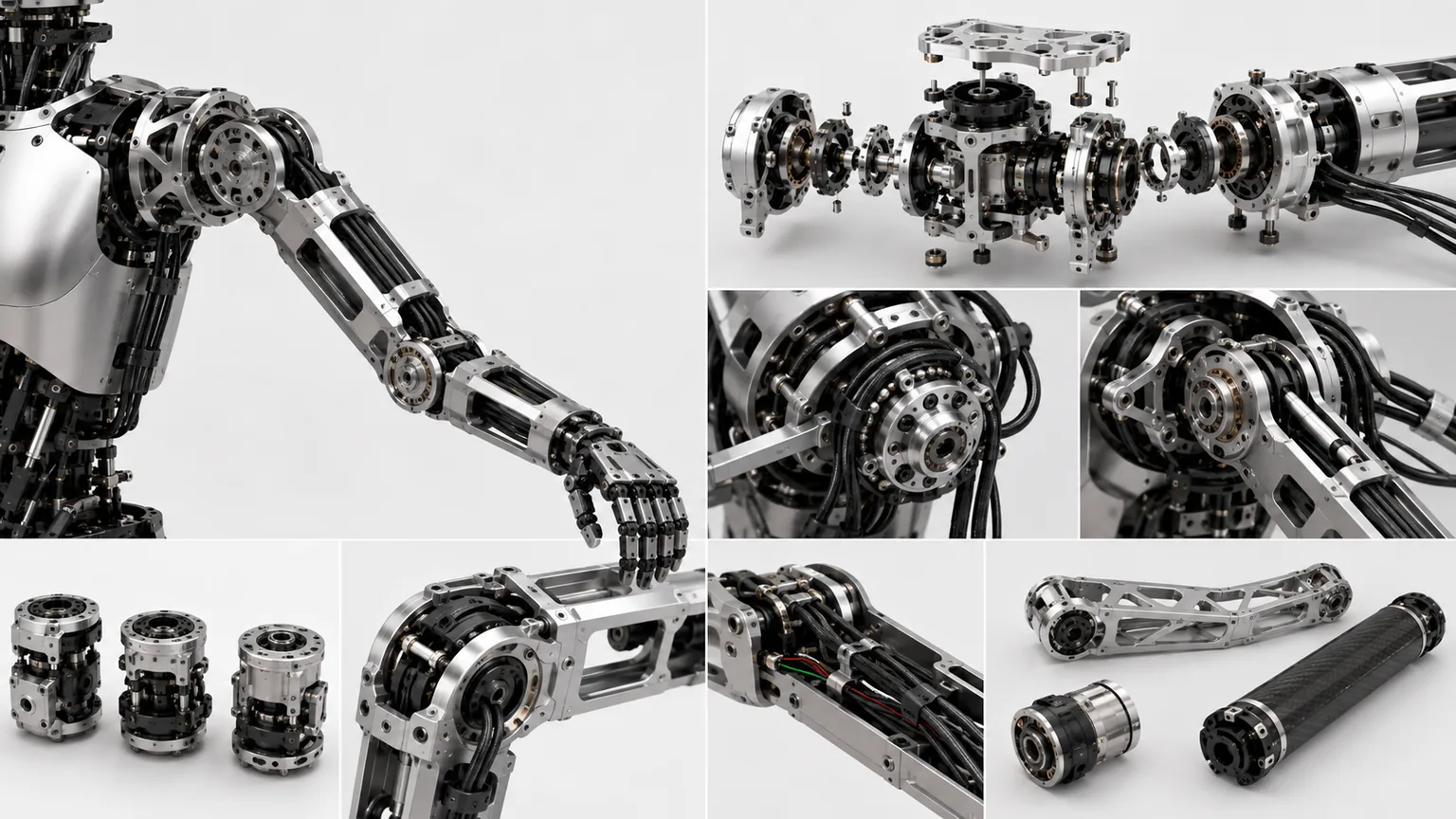
The shoulder and arm determine whether a humanoid can carry, assemble, use tools and collaborate with people.
The complete chain is:
Torso shoulder datum → multi-axis shoulder → upper-arm load path → elbow → forearm interface → wrist and hand pose
| Module | Main function | Manufacturing focus |
|---|---|---|
| Shoulder base | Connect torso and shoulder | Datums, shoulder width and stiffness |
| Three-DoF shoulder | Raise, abduct and rotate arm | Axis geometry, interference and backlash |
| Upper-arm frame | Connect shoulder and elbow | Low mass, bending/torsional stiffness and harness |
| Elbow | Flexion and selected forearm motion | Axis, thrust, stiffness and stops |
| Forearm interface | Connect wrist, hand and sensors | Mass, center of gravity and module location |
| Harness and sensing | Power, data, position and torque | Bend, twist, zero and service |
1. Why the Shoulder Is Harder Than a Single Industrial-Robot Joint
Industrial robots normally have more space for motors, reducers and harnesses. A humanoid shoulder is constrained by shoulder width, chest shape, bilateral arm spacing and human-like proportions.
It must provide:
- large three-dimensional motion;
- no structural interference close to the torso;
- adequate stiffness during raised and extended poses;
- mirrored bilateral consistency;
- compact motors, reducers, bearings and sensors;
- harness bend and twist across several axes;
- compliance or overload protection;
- serviceable modular construction.
Small axis-angle or location errors are amplified by upper-arm and forearm length into visible hand error.
2. Shoulder Degrees of Freedom and Architecture
| Architecture | Characteristic | Advantage | Main risk |
|---|---|---|---|
| Serial three-axis shoulder | Three one-axis modules stacked | Clear model and modularity | Width and inertia |
| Near-intersecting axes | Rotational axes concentrated at shoulder center | Ball-joint-like kinematics | High manufacturing and assembly accuracy |
| Offset axes | Creates space for motors and reducers | Packaging flexibility | More complex model and interference |
| Differential / coupled shoulder | Multiple actuators jointly generate motion | Compact, high power density | Decoupling, backlash and calibration |
| Remote tendon drive | Motors located in chest or upper arm | Low local shoulder mass | Friction, stretch and pretension |
| Parallel / spherical mechanism | Multiple links control pose | Compact and stiff in selected directions | Part count, kinematics and service |
Engineering review should identify which joints are independently driven, coupled, compliant, retained or allowed to fall on power loss, and how every axis is zeroed and calibrated.
3. Select Five, Six or Seven Arm Axes from the Task
General spatial manipulation requires control of:
- three position components: X, Y and Z;
- three orientation components: roll, pitch and yaw.
Six degrees of freedom are therefore the theoretical minimum for independently controlling complete hand position and orientation.
| Arm axis count | Capability boundary | Advantage | Manufacturing and production cost |
|---|---|---|---|
| 5 axes | Handling with relaxed orientation constraints | Light, lower cost and simpler control | One independent orientation component is missing |
| 6 axes | Complete hand position and orientation in theory | Minimum complete general-purpose arrangement | Limited escape from singularities, limits and elbow interference |
| 7 axes | Elbow posture can change while hand pose remains fixed | Better obstacle avoidance and dual-arm coordination | More actuators, mass, heat, wiring, backlash and calibration |
The seventh axis provides kinematic redundancy. It can help avoid the torso, head, shelves, walls and the opposite arm while preserving the required hand pose.
A seventh axis is not an unconditional upgrade. Every added axis introduces another reducer, bearing set, harness segment, heat source, lost-motion contribution and calibration parameter. Specifications should identify where the extra freedom is located and what task benefit it provides.
4. A Human-Like Shoulder Does Not Need a Fixed Center of Rotation
Conventional robot shoulders often place three rotational axes at one fixed point. Human shoulder motion also includes scapular and clavicular movement, so the effective center changes with posture.
The cybernetic-shoulder research proposed a three-DoF closed-chain mechanism that:
- imitates compound human shoulder motion;
- does not use one fixed center of rotation;
- generates output posture through a closed kinematic chain;
- provides a structural basis for mechanical compliance and actuation redundancy.
This can create more human-like motion close to the head and chest, but it is harder to manufacture and calibrate than three standard serial joints.
| Fixed-center shoulder | Moving-center closed-chain shoulder |
|---|---|
| Simple kinematics and fewer parameters | Larger human-like workspace |
| Standard actuator modules are easy to stack | Link lengths and joint locations interact |
| Compliance requires added series elements | Closed chain can support integrated compliance |
| Errors accumulate mainly along three axes | Tolerance error can create internal force and binding |
Key CTQs include closed-chain link centers, spherical and universal-joint centers, branch length, preload, interference through travel, instantaneous center trajectory and input-to-output calibration across many poses.
5. A Double-Spherical Shoulder Adds Shoulder-Girdle Motion
Double-spherical-joint research combined two spherical motion centers so that the shoulder could provide more than upper-arm rotation. Follow-up prototypes reported a large workspace and torso-like compensation without simply adding more serial joints.
Potential benefits include:
- greater bilateral arm workspace;
- better motion close to the chest and head;
- shoulder-girdle contribution to carrying, turning and whole-body coordination.
The mechanism is not simply two standard ball bearings stacked together. The geometry and constraints between two spherical centers determine the motion.
| Double-spherical CTQ | Failure effect |
|---|---|
| Distance and direction between spherical centers | Actual path differs from model |
| Mirrored bilateral geometry | Asymmetric arm workspace |
| Bearing and spherical-joint clearance | Moving shoulder center and hand wobble |
| Closed-chain link length | Binding, internal force and pose error |
| Chest mounting datum | Shoulder width and height error |
| Harness allowance | Tension, rubbing and fatigue |
| Multi-center calibration | Poor hand-path prediction |
This route is suitable when human-like workspace justifies greater part count, assembly complexity and maintenance burden.
6. Programmable Passive Compliance Responds Faster Than Software Alone
Active compliance is programmable but depends on sensing, sampling, communication and control delay. Mechanical springs and compliant links respond directly to fast impact, but fixed stiffness cannot suit every task.
Programmable passive compliance uses a closed chain with:
- redundant actuators;
- elastic members;
- adjustable pretension;
- nonlinear force-displacement behavior;
- controlled tension distribution.
Changing elastic preload changes equivalent shoulder stiffness by direction. The design target is a spatial stiffness distribution or compliance ellipsoid, not one scalar spring rate.
| Task state | Desired compliance |
|---|---|
| Fast free-space motion | Moderate stiffness and low vibration |
| Precision insertion | High task-direction stiffness and compliant contact direction |
| Human interaction | Lower collision-direction stiffness |
| Heavy carrying | High gravity and torsional stiffness |
| Dynamic swing | Controlled elastic energy storage and release |
| Power loss | Predictable mechanical state |
Production control must include elastic-material lot, stiffness curve, preload, branch symmetry, thermal aging, creep, hysteresis, energy loss and recalibration after replacing compliant parts.
7. Manufacturing Lessons from Tesla Optimus Public Disclosures
Tesla publicly describes Optimus as a general-purpose bipedal robot for unsafe, repetitive or boring work, supported by vision, planning and physical-world interaction. Tesla has not publicly disclosed a complete current shoulder-axis layout, reducer section or shoulder tolerance chain, so a definitive internal BOM should not be inferred from videos.
Its public 2026 information still shows several relevant manufacturing principles.
7.1 Bespoke actuators instead of one universal module
Tesla job postings separate actuator hardware validation, geartrain development, bespoke motor design, manufacturing engineering and system testing. Shoulder and elbow actuators should therefore be jointly optimized for torque-speed duty, mass, thermal state, backdrivability, efficiency, life, cost and takt time.
7.2 Put actuator test and calibration into the production system
Public roles reference dynamometers, electrical testers and motor-calibration equipment. A shoulder-arm production line should check:
- back-EMF, phase resistance and sensors;
- no-load friction and breakaway torque;
- torque-speed-efficiency curves;
- forward/reverse lost motion;
- temperature rise and protection;
- encoder zero and scale;
- brake or power-off behavior;
- vibration, noise and life;
- serial-number-linked test data.
7.3 Co-develop motors, gears, electronics and structure
Tesla’s public roles cover bespoke motors, geartrains, actuator integration, electrical-system packaging and robot validation. Mechanical interfaces affect air gaps, bearing preload, heat flow, harness force and sensor zero, so these systems cannot be optimized independently.
7.4 Shift from prototype to automated production
Tesla’s Q2 2026 update stated that first-generation Optimus production lines were being installed in anticipation of production in 2026. The important manufacturing lesson is the shift toward process development, automation, online inspection, calibration, traceability, takt time and yield.
| Production review | Required answer |
|---|---|
| Part commonality | Does commonality reduce cost or add distal mass? |
| Automated assembly | Are bearings, reducers, encoders and harnesses directionally defined? |
| Datum transfer | Can part, actuator, arm and robot datums be related? |
| Online inspection | Which CTQs require 100% inspection? |
| End-of-line calibration | Can load, parameter generation and storage be automated? |
| Repairability | Can an actuator be replaced without dismantling the entire arm? |
| Traceability | Are parts, torque, preload, curves and software linked? |
| Design iteration | Do new revisions preserve critical interfaces and fixtures? |
The useful lesson is not to copy Tesla’s appearance, but to treat bespoke actuators, test calibration, structural integration and scale manufacturing as one engineering system.
8. Shoulder Axis Geometry Determines Full-Arm Accuracy
A three-degree-of-freedom shoulder normally includes:
- forward/backward swing;
- lateral abduction;
- upper-arm internal/external rotation.
The axes may theoretically intersect or have defined offsets. Control:
- bearing-seat coaxiality;
- reducer pilot and face;
- axis direction and included angle;
- axis intersection or specified offset;
- shoulder base to torso datum;
- left-right mirrored relationship;
- full-travel interference and stops.
| Axis error | Hand-level result |
|---|---|
| Shoulder-axis direction error | Arm motion plane rotates |
| Incorrect axis intersection | Hand path differs from model |
| Bilateral shoulder-height error | Asymmetric dual-arm manipulation |
| Upper-arm rotation eccentricity | Elbow and wrist pose coupling |
| Shoulder-base deflection | Loaded hand-position drift |
Final assembly needs multi-pose identification of actual axes and kinematic parameters.
9. Shoulder Load Is More Than Rated Hand Payload
The shoulder carries:
- upper arm, forearm and hand mass;
- bending moment from hand payload;
- arm acceleration inertia;
- coordinated dual-arm loads;
- push, pull, support and tool reaction;
- collision and fall impact;
- harness and compliant-element torque.
Load cases should include:
- arm hanging;
- arm extended forward;
- arm abducted sideways;
- bent-elbow carrying;
- dual-arm carrying;
- fast acceleration and stop;
- collision and power loss;
- long-duration pose holding.
The same hand payload can produce very different shoulder torque depending on pose and mass distribution.
10. Balancing Upper-Arm Mass and Stiffness
Common routes include:
- thin-wall aluminum box frames;
- CNC aluminum skeletons with lightweight covers;
- magnesium frames;
- local titanium connectors;
- CFRP tubes or sheets with metal ends;
- additively manufactured hollow structures.
| Feature | Purpose | Manufacturing risk |
|---|---|---|
| Closed box section | Efficient bending and torsional stiffness | Limited internal access |
| Open skeleton | Low mass and service access | Lower torsional and impact resistance |
| Local ribs | Support bearings and fasteners | Stress concentration and distortion |
| Metal ends + CFRP | Reduce long-member mass | Bonding, inserts and thermal mismatch |
| Removable side cover | Harness and drive service | Repeat location and shell distortion |
| Topology optimization | High specific stiffness | Tool access, surface and fatigue validation |
Distal mass should be reduced first while retaining stiffness where shoulder, elbow and external loads enter the frame.
11. CTQs for the Upper-Arm Frame and Bearing Seats
| CTQ | Effect | Control |
|---|---|---|
| Shoulder interface | Arm pose and load input | Face, pilot and dowels |
| Effective arm length | Hand workspace | Datum dimension and pairing |
| Elbow-axis location | Shoulder-elbow kinematics | CMM and combined fixture |
| Bearing-seat coaxiality | Friction, heat and life | Single setup or combined finishing |
| Side-plate parallelism | Binding and axial play | Assembly-state measurement |
| Local wall thickness | Stiffness and machining distortion | Blank and wall inspection |
| Harness channel | Rub, pinch and service | Full-travel physical check |
| Cover interface | Appearance and collision clearance | Position and repeated assembly |
Thin-wall machining requires controlled clamping, sequencing, symmetric material removal and stress management.
12. Why the Elbow Is More Than a Simple Single-Axis Module
The elbow is mainly a flexion joint, but some humanoids also need forearm rotation or compensation through shoulder and wrist.
Manufacturing focus includes:
- elbow axis relative to upper-arm and forearm datums;
- reducer and bearing support;
- axial thrust and lateral clearance;
- hard stops;
- position and torque sensing;
- harness guidance during flexion;
- pinch and collision protection;
- repeatable zero after service.
The elbow sits in the middle of the hand load path and carries both bending moment and dynamic arm inertia.
13. Select Reducer, Bearings and Support as One System
| Route | Advantage | Main risk |
|---|---|---|
| Harmonic reducer | Compact and high ratio | Flexspline life, elasticity and changing lost motion |
| Planetary reducer | Efficient and load capable | Multi-stage backlash, lubrication and noise |
| Cycloidal reducer | Impact and torque capability | Volume, vibration and precision |
| Remote synchronous belt | Flexible motor location | Tension, wear and guarding |
| Tendon drive | Motor can move into chest or arm | Friction, stretch and pretension |
| Direct drive | Low backlash and direct control | Motor size, heat and peak current |
Check output-bearing overturning load, support span, housing elasticity, motor-plus-reducer mass, heat and post-service calibration—not reducer torque alone.
14. How Backlash, Stiffness and Friction Affect the Hand
Hand error can come from:
- three shoulder-axis lost motions;
- elbow backlash;
- bearing clearance;
- frame and flange elasticity;
- belt or tendon stretch;
- bolted-joint microslip;
- control deadband;
- harness reaction;
- temperature.
Use three test levels:
- single-joint friction, backlash and stiffness;
- unloaded full-arm multi-pose repeatability;
- loaded arm tests in forward, side and bent-elbow poses.
Report hand displacement versus external force, direction dependence, temperature drift and repeatability.
15. Shoulder and Elbow Harnesses Are High-Life-Risk Areas
The shoulder harness sees:
- multi-axis twist;
- large sweeping motion;
- rubbing against housings and drives;
- tension at extreme poses;
- interaction between power and signal lines.
The elbow sees high-cycle repeated bending.
Define fixed and moving ends, neutral length, minimum bend radius, accumulated twist, edge clearance, strain relief, connector direction, protective guides, module-removal sequence and extreme-pose margin.
Life testing should reproduce combined shoulder-elbow trajectories.
16. Torque, Position and Temperature Sensor Interfaces
Common sensing includes:
- motor encoder;
- output absolute encoder;
- joint torque sensor;
- current and temperature sensing;
- arm IMU;
- mechanical zero reference.
| Sensor-interface CTQ | Main risk |
|---|---|
| Mounting-face flatness | Uneven loading and zero drift |
| Center and axis | Component coupling |
| Bolt preload | Sensitivity variation |
| Cable strain relief | Noise and terminal damage |
| Distance from heat source | Poor thermal compensation |
| Anti-rotation feature | False displacement |
Calibrate sensors under final preload and representative temperature.
17. Managing Mirrored Left-Right Consistency
Control:
- shoulder datum height;
- shoulder-center spacing;
- effective upper-arm and forearm lengths;
- elbow-axis direction;
- stop angles;
- harness allowance;
- sensor zero;
- software sign convention;
- fastener and assembly order.
Use color coding, QR identification, keys or non-interchangeable interfaces to prevent mirrored-part mistakes.
18. Collision and Power-Loss Behavior Must Be Designed Early
Consider:
- collision detection and torque limits;
- compliant control or series elasticity;
- hard and soft stops;
- rounded covers and pinch points;
- arm drop on power loss;
- inspectable datums after overload;
- replaceable sacrificial modules;
- emergency backdriving and service posture.
Safety requires structure, reducer backdrivability, brakes, elasticity and control together.
19. Full-Arm Calibration Goes Beyond Motor Zero
The chain is:
Motor encoder → reducer output → actual shoulder axes → elbow axis → forearm interface → hand pose
Calibration should include:
- torso and shoulder-base datum;
- motor direction and encoder scale;
- three shoulder-axis direction, intersection or offset;
- elbow axis and zero;
- effective upper-arm and forearm length;
- forward/reverse backlash;
- loaded elastic deflection;
- temperature and harness reaction;
- bilateral mirror consistency;
- post-service repeat location;
- parameter-to-serial-number binding.
Loaded calibration is essential because unloaded hand accuracy does not guarantee loaded accuracy.
20. Prototype-to-Production Route
- 01Define TasksCarrying, tools, collaboration, speed, payload and workspace.
- 02Select Shoulder ArchitectureSerial, intersecting, offset, coupled or tendon driven.
- 03DynamicsShoulder/elbow torque, speed, inertia, impact and heat.
- 04Engineering PrototypeAxes, reducers, frames, harnesses and sensors.
- 05Full-Arm CalibrationAxes, zero, hand pose, backlash and load compensation.
- 06Life and Abnormal CasesHarness, thermal, collision, power loss and service.
- 07Freeze ProductionCTQs, fixtures, inspection, traceability and configuration.
21. Information Required for RFQ and Engineering Review
| Category | Recommended information |
|---|---|
| Robot | Height, shoulder width, torso and total mass |
| Motion | Shoulder/elbow DoF, range, speed and workspace |
| Loads | Hand payload, tool reaction, dual-arm carrying and collision |
| Transmission | Motors, reducers, belts, tendons or direct drive |
| Interfaces | Torso, shoulder, upper arm, elbow, forearm and wrist |
| Sensors | Encoders, torque, IMU, temperature and zero |
| Harness | Power, data, bend radius and life cycles |
| Material/finish | Frames, shafts, bearing seats, fasteners and lubrication |
| Mass target | Shoulder, upper arm, forearm and center of gravity |
| Validation | Stiffness, backlash, thermal, collision, life and calibration |
| Traceability | Parts, assembly, software and bilateral configuration |
Frequently Asked Questions
Does a humanoid shoulder always need three degrees of freedom?
No. Three degrees of freedom approximate the principal human shoulder motions and expand hand workspace, but they also increase actuator count, shoulder width, mass, harness complexity, control and calibration. The architecture should match the task, payload and robot envelope.
Why can hand-position error remain large when every shoulder part passes inspection?
Multi-axis shoulder geometry, bearing preload, reducer backlash, arm-frame elasticity, elbow-axis error, sensor zero and harness reaction are amplified at the hand. Full-arm pose and loaded calibration are required in addition to part inspection.
Why do arm harnesses fail around the shoulder and elbow?
The shoulder combines multi-axis rotation while the elbow undergoes repeated bending. Without controlled neutral length, bend radius, twist allowance, fixing points and strain relief, the harness can rub, pinch or fatigue. Life testing must reproduce real shoulder-elbow motion.
What is the most important validation before humanoid arm production?
Validate full-pose workspace, loaded stiffness and backlash, shoulder and elbow axes and zero positions, hand-position repeatability, harness life, thermal rise, collision and power-loss behavior, module replacement repeatability and recalibration capability.
