
In This Article
Direct Answer
Joint-actuator quality control should not start with the question, “Which tolerance is the smallest?” It should start with a functional question:
Which geometric relationships, when shifted, create friction, noise, backlash, temperature rise, position error or reduced service life?
For most integrated joints, CTQs originate from four functional chains:
- Rotation-axis chain: whether the motor, reducer, output bearing and output flange share the intended axis;
- Load-transfer chain: how radial, axial and overturning loads move from the output flange into the bearings and housing;
- Axial-location chain: how shoulders, bearing widths, spacers, reducer faces and end caps establish axial position and preload;
- Encoder-feedback chain: how the true output angle is transferred through the encoder mounting geometry to the controller.
Only after these chains are understood can the team decide which features are CTQs, which datum system is appropriate, which process creates the requirement and how it must be inspected.
1. A CTQ is not a list of tight tolerances
A CTQ is a small number of characteristics with a direct effect on function, assembly, reliability or safety. It is not automatically:
- every dimension carrying a tolerance;
- every dimension shown to several decimal places;
- every feature measured on a CMM;
- every dimension highlighted by a customer.
A feature deserves CTQ status when deviation can do at least one of the following:
- shift the rotation center or load path;
- change bearing fit, preload or clearance;
- distort reducer mounting conditions;
- change encoder gap or feedback quality;
- cause interference, binding or looseness;
- materially affect noise, temperature, accuracy or life.
The correct sequence is therefore:
Functional failure mode
→ Assembly and load relationship
→ Critical geometric relationship
→ Drawing requirement
→ Manufacturing and verification method
Starting from the drawing and working backward often creates a long CTQ list without a clear functional reason.
2. The four functional chains inside a joint actuator
2.1 Rotation-axis chain
A typical chain may include:
Motor rotor axis
→ Wave-generator or input-gear axis
→ Reducer datum axis
→ Output-bearing axis
→ Output-flange axis
Misalignment can cause:
- input-side side loading;
- rough reducer motion;
- uneven bearing loading;
- output runout;
- increased friction and temperature;
- premature life reduction.
Reducer installation guidance commonly requires concentric and perpendicular mounting relationships and warns against housing distortion that pushes a circular spline out of round. This makes the reducer locating seat a core functional datum rather than an ordinary mounting feature.
2.2 Load-transfer chain
Loads at the output flange must pass through a physical support path:
Output flange
→ Output shaft or flexspline
→ Output support bearing
→ Bearing seat
→ Joint housing
→ Robot link
If the bearing span is insufficient, the seat distorts or the flange-face relationship is unstable, overturning moment can create elastic axis displacement. The part may pass static dimensional inspection but still show poor loaded positioning.
Load-path CTQs may therefore include:
- bearing-seat stiffness;
- shoulder contact area;
- output-flange face stiffness;
- deformation of thin housing walls;
- contact condition between bolted and locating faces.
2.3 Axial-location and preload chain
Axial position is commonly closed through several parts:
Housing datum face
→ Bearing shoulder
→ Bearing width
→ Spacer or retaining ring
→ Reducer face
→ End cap
This is a tolerance-stack problem, not a single-dimension problem. Independent part tolerances may combine into:
- excessive preload, increasing starting torque and temperature;
- insufficient preload, allowing axial play and impact;
- changing encoder axial gap;
- housing distortion after the end cap is tightened.
The axial chain should therefore define the closed dimension, adjustment method and assembly acceptance method. Selective assembly, controlled shims or press-force monitoring may be required instead of relying only on individual dimensions.
2.4 Encoder-feedback chain
The measured angle must represent the true output angle. A typical feedback chain is:
Output shaft or rotor datum
→ Encoder disk or magnetic ring
→ Readhead mounting face
→ Readhead gap
→ Controller signal
Feedback stability can be affected by:
- radial eccentricity of the scale;
- axial runout of the mounting face;
- changing readhead gap;
- non-perpendicular mounting geometry;
- thermal distortion of the housing;
- cable load moving the readhead.
The encoder interface should therefore be checked in assembly with both mechanical runout and electrical signal quality, not by mounting-hole dimensions alone.
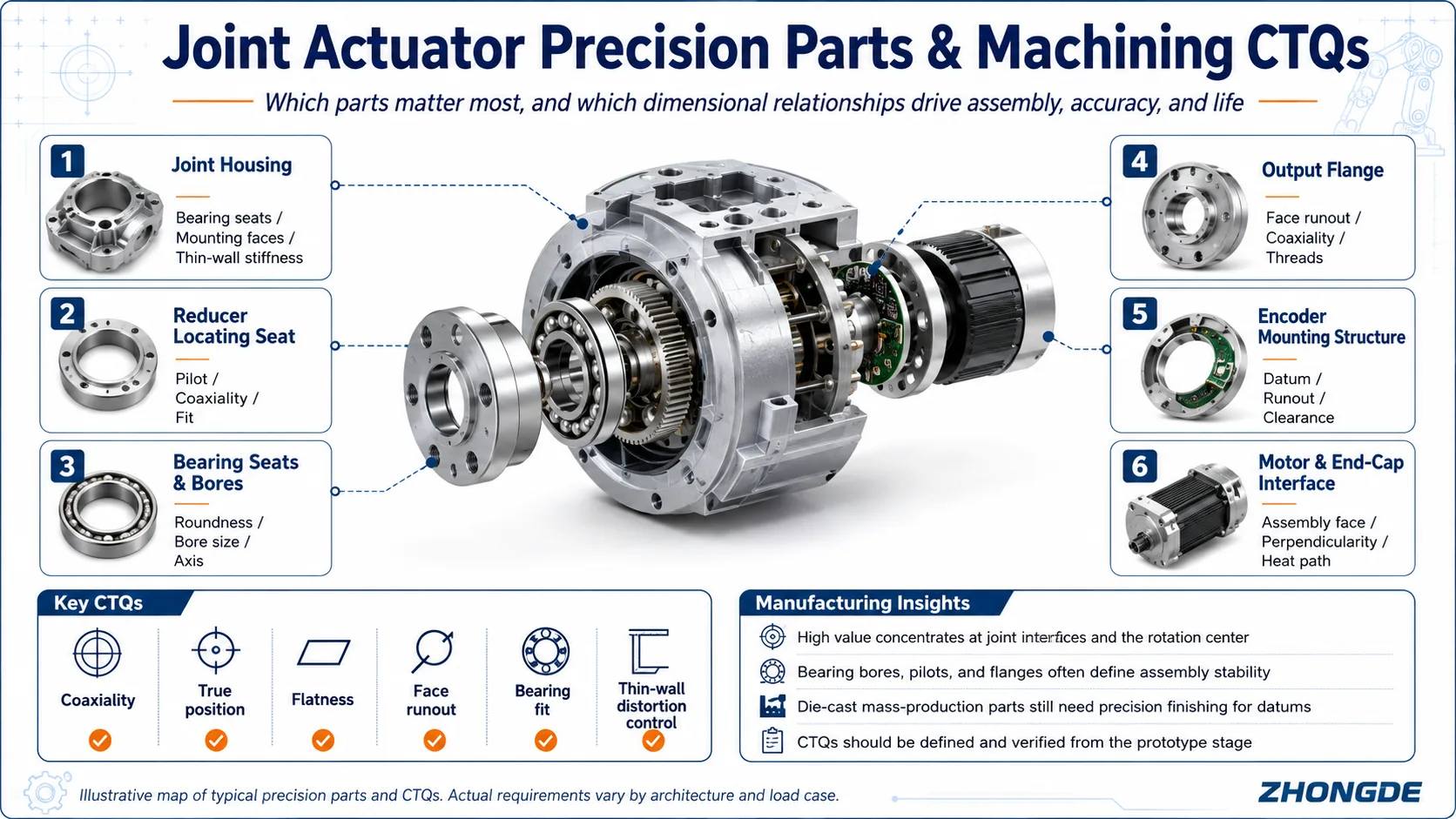
3. The actual CTQs of six precision-part groups
3.1 Joint housing
A joint housing may simultaneously support bearings, locate the reducer, mount the motor, mount the encoder and conduct heat.
Typical CTQs include:
- bearing-bore size, roundness and cylindricity;
- the common-axis relationship of separated support bores;
- reducer-pilot location relative to the main axis;
- orientation of the motor mounting face to the axis;
- relationship between output-side and robot-link mounting faces;
- distortion of thin walls under clamping and assembly.
A common failure is that the free-state part passes inspection but distorts after bearings, the reducer or an end cap are tightened. When needed, inspection should include a controlled clamped or simulated-assembly condition.
3.2 Reducer locating seat
The key questions are not cosmetic diameter and surface appearance. They are:
- Does the pilot remain round?
- Is its axis aligned with the output support axis?
- Is the mounting face oriented correctly to the datum axis?
- Does the bolt pattern force the reducer off center?
- Does tightening distort the reducer interface?
For strain-wave gearing, pilot distortion and eccentricity can directly affect smoothness and life.
3.3 Bearing seats and bores
A bore within size tolerance does not automatically create the correct bearing fit. The seat should be evaluated for:
- dimensional tolerance;
- roundness;
- cylindricity;
- surface texture;
- shoulder orientation;
- the relationship between two bearing axes;
- fit at operating temperature;
- housing distortion after installation.
The fit class should be selected from load direction, which ring sees rotating load, material and temperature. Applying one fit to every joint is not a sound design rule.
3.4 Output flange
The output flange joins motion accuracy with external assembly. Typical CTQs include:
- locating diameter or bore relative to the rotation axis;
- output-face runout;
- mounting-hole-pattern position;
- thread depth and effective engagement;
- flange-face flatness;
- face stiffness under load.
Controlling only flange outside diameter cannot prevent periodic link wobble if face runout and hole-pattern position are uncontrolled.
3.5 Encoder mounting structure
Separate the encoder geometry into two datum groups:
- rotating datum: disk, magnetic ring or rotor mounting features;
- stationary datum: readhead, sensor PCB or bracket mounting features.
Typical CTQs include:
- radial eccentricity of the rotating scale;
- axial runout of the scale face;
- readhead position;
- scale-to-readhead gap;
- orientation of the readhead mounting face to the axis;
- signal amplitude, phase and repeatability after assembly.
Mechanical inspection and electrical signal verification complement each other; neither replaces the other.
3.6 Motor and end-cap interface
This interface affects axis alignment, heat transfer and assembly stress. Typical CTQs include:
- stator locating surface relative to the main axis;
- end-cap mounting-face flatness;
- common-axis relationship between end-cap and housing bearing bores;
- end-cap distortion after bolt tightening;
- thermal contact surface condition;
- cable-exit and sealing-feature location.
4. How should the datum system be built?
There is no universal datum template, but one principle should guide the design:
Drawing datums should represent how the part is functionally located in the real assembly.
A common housing concept may use:
- Primary datum A: a stable assembly face or major support face;
- Secondary datum B: the main bearing bore, locating pilot or the functional axis derived from it;
- Tertiary datum C: a hole, slot or side face used for clocking.
The actual order depends on architecture. If the bearing bore directly defines the rotation axis and the face only establishes axial location, the functional axis may deserve higher datum priority.
Four forms of consistency are required:
- Design consistency: tolerance requirements refer to functional datums;
- Manufacturing consistency: related features are finished in one setup or through controlled datum transfer;
- Inspection consistency: measurement programs reconstruct the drawing datum system rather than selecting the easiest setup;
- Assembly consistency: the real assembly locating method does not contradict the drawing datum concept.
If the design, machining, inspection and assembly teams each create their own datum system, individually accepted parts can still fail in assembly.
5. Coaxiality, true position and runout are not interchangeable
| Control | Functional purpose | Typical use |
|---|---|---|
| True position | Locates holes, axes or hole patterns from datums | Bolt patterns, bearing-bore location, encoder holes |
| Common-axis control | Aligns multiple rotating features | Two bearing bores, reducer pilot and output axis |
| Circular or total runout | Limits surface motion during rotation | Output flange face, encoder scale, locating diameter |
| Perpendicularity | Orients a face to an axis | Motor face, reducer mounting face |
| Flatness | Controls the shape of one face | End-cap face, flange face, thermal interface |
The symbol should follow the failure mode:
- periodic wobble at the rotating output is more directly expressed by face runout than by flatness alone;
- hole-pattern assembly problems are better controlled by true position than by coaxiality;
- two separated support bores require a common-axis relationship, not only independent size tolerances.
6. How should the machining route be designed around CTQs?
6.1 Prototype stage
Billet CNC is common during prototyping. The goal is not the lowest unit cost, but verification of:
- datum logic;
- measurability of tolerances;
- thin-wall distortion;
- assembly sequence;
- bearing and reducer interface behavior;
- encoder signal stability after assembly.
Related bores, pilots and faces should be finished in one setup whenever practical to reduce datum-transfer error.
6.2 Pilot stage
For pilot production, the following should be frozen:
- blank condition;
- roughing allowance;
- semi-finishing and stabilization sequence;
- fixture locating points and clamping force;
- tool-life rules;
- measurement program and acceptance rules.
The focus moves from single-part acceptance to trends across lots, tool wear and temperature.
6.3 Mass-production stage
Production structures may move to die-cast, forged or other near-net-shape blanks. Datum creation must then be replanned:
- Establish stable process datums;
- Machine main bearing bores and reducer locating features;
- Finish the output flange and encoder interface from the same or a controlled related datum;
- Machine secondary hole patterns and cosmetic features last.
Parting lines, draft, local porosity and residual stress in formed blanks can affect precision finishing, so a production process cannot simply copy a billet prototype program.
7. How should each CTQ be inspected?
No single instrument covers every CTQ.
| CTQ | Preferred method | Key caution |
|---|---|---|
| Bore size and fit | Air gauge, bore gauge, CMM | Temperature, measurement depth and form error matter |
| Roundness and cylindricity | Roundness or form instrument | A small number of CMM points may be insufficient |
| Position and axis relationship | CMM, precision mandrel fixture | Datum reconstruction must match the drawing |
| Face runout | Precision mandrel or rotary fixture with indicator | Simulate the true rotation datum |
| Flatness and perpendicularity | CMM, surface instrument or precision plate | Clamping changes thin-wall results |
| Encoder gap and signal | Dedicated gap gauge plus signal test | Mechanical acceptance does not guarantee signal acceptance |
| Preload and friction | Press-force curve, starting torque, no-load current | Link results to temperature and lubrication state |
For critical bores, retain both dimensional and functional data when possible:
- size and roundness;
- bearing installation force;
- starting torque after assembly;
- no-load current and temperature rise;
- output runout.
This separates part-machining problems from assembly or system-matching problems.
8. How do CTQs enter the control plan from prototype to production?
Once defined, a CTQ should enter one control chain:
Design requirement
→ Drawing and datum system
→ PFMEA failure analysis
→ Process and fixture
→ Inspection method
→ Measurement-system confirmation
→ Process capability
→ Functional assembly verification
→ Lot traceability
Control intensity can change by stage:
| Stage | Typical control approach |
|---|---|
| Prototype | High inspection coverage, complete CMM report, functional assembly verification |
| Pilot | Frozen fixtures and programs, first-piece plus patrol checks, trend analysis |
| Production | Capability monitoring, CTQ sampling, functional test and traceability |
Capability indices are meaningful only when the process and measurement system are stable. If the fixture, material or inspection method keeps changing, a Cpk value alone does not prove production readiness.
9. What should an executable CTQ matrix contain?
An effective CTQ matrix needs more than a tolerance value.
| Field | Purpose |
|---|---|
| Function | What the feature supports |
| Failure mode | What happens when it deviates |
| Feature and tolerance | Exact drawing control |
| Datum | Functional datum used for evaluation |
| Creation step | Process operation that establishes it |
| Inspection | Instrument or fixture used |
| Frequency | First-piece, 100 percent, patrol or sample |
| Reaction plan | Isolation, recheck and corrective action |
| Functional verification | Assembly, torque, signal or thermal test |
Example:
| Functional chain | Feature | Typical CTQ | Verification |
|---|---|---|---|
| Rotation axis | Two bearing bores | Size, roundness, common axis | Air gauge, form instrument, CMM |
| Reducer location | Pilot and mounting face | Location, orientation, roundness | CMM, form measurement |
| Output chain | Output flange | Face runout, hole-pattern position | Rotary fixture, CMM |
| Encoder feedback | Scale and readhead mounting | Eccentricity, runout, gap | Runout fixture, gap gauge, signal test |
| Axial location | Bearing shoulder and end cap | Closed dimension, preload | Dimensional inspection, press force, starting torque |
10. What design inputs should accompany an RFQ?
A correct CTQ plan usually needs more than the part drawing:
- joint section or assembly relationship;
- bearing type, fit and preload concept;
- reducer model and mounting requirements;
- radial, axial and overturning loads at the output;
- encoder type and permitted installation gap;
- assembly sequence and tightening method;
- operating temperature and heat path;
- target noise, backlash, life and repeatability;
- prototype, pilot and production quantities;
- planned billet, die-cast, forged or other blank route.
Without this information, a supplier can machine the drawing but cannot determine whether the tolerances truly protect system function.
Conclusion
Joint-actuator CTQs are fundamentally controls on four functional chains:
Rotation-axis chain
+ Load-transfer chain
+ Axial-location chain
+ Encoder-feedback chain
The housing, reducer seat, bearing bores, output flange, encoder interface and motor end cap matter because they jointly define the rotation center, support stiffness, preload state and feedback accuracy.
The correct response is not to add more tight tolerances. It is to:
derive CTQs from function, connect design and manufacturing with a consistent datum system, and verify real system behavior through inspection and assembly testing.
FAQ
Where should joint-actuator CTQ definition begin?
It should begin with function and assembly relationships, not by selecting a few tight tolerances from an existing drawing. First identify the rotation axis, load path, axial location and encoder-feedback chain, and then determine which bores, pilots, faces and mounting features must become CTQs.
How should coaxiality, face runout and true position be selected?
They should be selected according to function. A common rotation axis calls for an axis-related control, rotating face wobble calls for face runout, and a hole pattern located from datums calls for true position. These controls are not interchangeable symbols.
Why can an assembly still bind or overheat when the bearing-bore size is within tolerance?
Bore size is only one condition. Roundness, cylindricity, the relationship between two bearing axes, housing distortion, press-fit method, bearing clearance and operating temperature all influence the actual fit and preload state.
What matters most in an encoder mounting structure?
The key is the stable relationship between the encoder measurement datum and the true output axis, including mounting-face orientation, radial eccentricity, axial runout, readhead gap and signal quality after assembly. Checking mounting-hole size alone is usually insufficient.
Can CTQ control differ between prototype and mass production?
The CTQ itself should not change arbitrarily, but the process route, fixturing and inspection frequency used to establish it can change. Prototypes may use billet CNC and extensive inspection, while production may use die-cast or forged blanks with precision finishing of critical features and capability-based sampling.
