
In This Article
Direct Answer
Data center liquid cooling uses a liquid to collect, transport and reject heat from IT equipment. It is not simply a method of placing water inside a server. It is a controlled heat-transfer chain:
Chip or Electronic Component → Liquid-Cooling Terminal → Coolant → Heat Exchanger → External Environment or Heat-Reuse System
The liquid-cooling terminal may be:
- A cold plate installed on a CPU, GPU or accelerator;
- A liquid heat exchanger attached to the rear of a rack;
- An immersion tank containing a server board or complete IT unit;
- A purpose-built liquid module for a selected power component.
The OCP Cooling Environments Project covers cold plates, CDUs, immersion, rear-door heat exchangers and heat reuse. This scope shows that liquid cooling is a family of system architectures rather than one product.
The ASHRAE AI Data Center Framework describes direct-to-chip cooling as an important route for AI and HPC. Warm-water designs and lower dependence on compressor-based cooling can also increase economization hours and reduce water demand in suitable climates. Actual efficiency depends on the combined design of the server, technology cooling system, facility water system and external heat-rejection equipment.
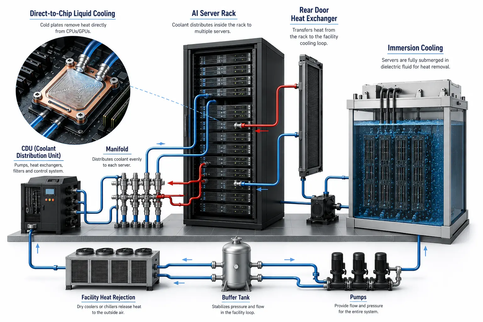
A data center liquid-cooling system must coordinate the server, technology cooling loop and facility heat-rejection equipment as one complete thermal chain.
1. Why AI Servers Increasingly Need Liquid Cooling
Traditional servers use fans and air to remove heat. Air cooling is mature and widely supported, but air has limited density and heat-carrying capacity.
Air-side constraints increase when:
- CPU, GPU and accelerator power rises;
- More high heat-flux regions appear inside one server;
- Rack power density increases;
- Fan speed, noise and power increase;
- Heat sinks, airflow paths and server height are constrained;
- Existing supply-air and return-air capacity approaches its limit.
Liquid can transport more heat with a smaller flow volume and can remove heat closer to the source. It is suitable for high heat-flux loads, but it does not automatically make a system efficient. Pumps, CDUs, heat exchangers, facility water, controls, redundancy and heat rejection all affect total energy use.
2. Are Liquid Cooling and Water Cooling the Same?
Not exactly.
Liquid cooling describes the use of a liquid as the primary heat-transport medium. The fluid may be:
- Controlled water;
- A water and ethylene-glycol or propylene-glycol mixture;
- A dedicated heat-transfer fluid;
- A dielectric fluid;
- A working fluid for a phase-change system.
Water cooling normally refers to water or a water-based fluid, but ordinary tap water is generally not allowed to circulate directly through server components.
A project should define:
- The technology-side fluid;
- The facility-side fluid;
- Whether a CDU heat exchanger separates the loops;
- Which metals, seals and tubing contact each fluid;
- Who manages fluid quality, concentration, temperature and maintenance.
3. Main Types of Liquid Cooling
Direct-to-Chip Cooling
Direct-to-chip cooling installs cold plates on CPUs, GPUs, accelerators or other high-power devices.
Coolant flows inside sealed tubing and cold-plate channels and does not contact the PCB. Typical parts include cold plates, hoses or hard tubes, quick disconnects, server manifolds, rack manifolds and a CDU.
This approach can retain a server and rack format close to conventional equipment and can support staged retrofits.
Immersion Cooling
Immersion cooling places a board or purpose-built server in a dielectric fluid. The fluid contacts many electronic components directly.
In single-phase immersion, the fluid remains liquid and circulates by pump or natural convection through a heat exchanger. In two-phase immersion, the fluid boils at electronic surfaces and is condensed back into liquid.
Immersion can reduce internal fans and conventional airflow structures, but it introduces new requirements for material compatibility, tanks, fluid management, equipment lifting and service procedures.
Rear-Door Heat Exchangers and Liquid-Assisted Rack Cooling
A rear-door heat exchanger uses liquid to absorb hot air leaving the server rack. The liquid does not enter the server, but the system reduces room air-cooling load.
This approach can provide a transition between conventional air cooling and direct-to-chip liquid cooling.
| Approach | Fluid Contact Boundary | Server Modification | Typical Application |
|---|---|---|---|
| Direct-to-chip | Inside cold plates and tubing | Medium | AI servers, HPC and existing-site upgrades |
| Immersion | Many electronic components | High | Purpose-built high-density clusters and new systems |
| Rear-door heat exchanger | Rack rear-door exchanger | Low | High-density rack retrofits and hybrid cooling |
| Liquid-cooled cabinet | Liquid modules inside a cabinet | Architecture dependent | Edge, modular and custom deployments |
4. How a Complete Liquid-Cooling System Works
A direct-to-chip heat path commonly includes:
- A chip generates heat;
- A TIM transfers heat to the cold plate contact surface;
- Internal cold-plate channels transfer heat into technology-side coolant;
- Server tubing carries fluid to a rack manifold;
- A CDU controls flow, pressure, temperature and loop separation;
- The CDU heat exchanger transfers heat to the facility water system;
- A dry cooler, cooling tower, chiller or other system rejects the heat;
- In suitable projects, heat may enter a heat-reuse system.
This path contains three boundaries:
| Boundary | Main Content |
|---|---|
| Inside IT equipment | Chip, cold plate, server tubing and sensors |
| Technology cooling system | Server manifold, rack manifold, QDs, CDU and technology-side coolant |
| Facility water system | Facility piping, pumps, heat rejection and heat reuse |
Different teams may use primary and secondary loop terminology in different ways. Server side and facility side are clearer terms for drawings and RFQs.
5. Key Liquid-Cooling Components
The OCP Cold Plate Project treats cold plates, tubing, manifolds, quick disconnects and CDUs as core elements of the direct-liquid-cooling ecosystem.
| Component | Main Function | Common CTQs |
|---|---|---|
| Cold plate | Collect heat from the chip | Flatness, roughness, channels, pressure drop and leakage |
| Server manifold | Distribute flow inside a server | Branch consistency, port position and cleanliness |
| Rack manifold | Connect multiple server branches | Hole pattern, flow balance, proof pressure and leakage |
| Quick disconnect | Support rapid connection and replacement | Sealing, orientation, flow resistance and cycle life |
| Hose and hard tube | Transport coolant | Inside diameter, bending, materials, permeation and cleanliness |
| CDU | Control technology-side coolant | Flow, pressure, temperature, heat transfer and redundancy |
| Valve and filter | Isolate, regulate and protect the loop | Flow resistance, particle capacity and service clearance |
| Sensor | Monitor temperature, pressure, flow and leakage | Accuracy, position, response and calibration |
| Leak-management structure | Detect and manage leakage | Coverage, drain path and false-alarm control |
| Heat exchanger and rejection equipment | Transfer heat out of the facility | Capacity, environmental range and controls |
6. Why the Cold Plate Is a Core Manufacturing Part
A cold plate is the terminal heat exchanger between the chip and coolant.
ASHRAE compares cold plates with terminal units in a distributed chilled-water system, but cold plates have specific boundaries for temperature, flow, pressure drop, material compatibility and cleanliness.
A cold plate commonly includes:
- A thermal contact base;
- Serpentine, parallel, pin-fin or microchannel passages;
- A cover or sealing layer;
- Inlet and outlet ports;
- Mounting holes and locating surfaces;
- Brazed, welded or mechanically sealed regions.
Cold-plate performance depends on the combined control of the thermal interface, channels, joining, ports, cleaning and functional testing.
7. What Is a CDU and Why Is It Important?
CDU means Coolant Distribution Unit.
A CDU may provide:
- Technology-side coolant circulation;
- Supply and return temperature control;
- Flow and pressure control;
- Isolation between the TCS and facility water loop;
- Heat exchange;
- Filtration and fill functions;
- Air removal;
- State monitoring;
- Pump, power or control redundancy;
- Remote alarms and data recording.
CDUs can be installed in-rack, beside the rack, in-row or in a central equipment area. Selection should consider capacity, redundancy, maintenance, space, noise, piping and facility conditions.
8. What Value Can Liquid Cooling Provide?
Higher Power-Density Capability
Liquid removes heat near the source and supports higher-power processors and racks within a limited space.
Reduced Airflow Demand
When more heat moves through liquid, server and room airflow loads can decrease. Fan removal still depends on residual heat.
More Economization and Heat-Reuse Opportunities
Higher coolant return temperatures can increase dry-cooler and economizer operation and may support building heating, hot-water or other heat-reuse applications.
Modular Expansion
Cold plates, manifolds, CDUs and facility interfaces can be expanded by server, rack or zone.
Each benefit must be validated through system data. The presence of liquid cooling alone does not prove the benefit.
9. What Problems Does Liquid Cooling Not Automatically Solve?
Liquid cooling does not automatically eliminate:
- Leakage risk;
- Corrosion and galvanic corrosion;
- Microchannel blockage;
- Coolant degradation;
- Material incompatibility;
- Trapped air;
- Pump failure;
- Sensor drift;
- Maintenance errors;
- Control-system faults;
- Insufficient facility capacity.
It converts some air-management challenges into fluid, material, sealing, cleanliness, monitoring and maintenance challenges.
10. Main Manufacturing CTQs
| CTQ Category | Typical Requirement |
|---|---|
| Thermal interface | Flatness, roughness, total height and mounting load |
| Channel | Width, depth, wall thickness, distribution and local restriction |
| Hydraulic performance | Flow range, pressure drop and branch consistency |
| Sealing | Leak performance, proof pressure and cycling reliability |
| Materials | Compatibility among metals, seals, coolant and coatings |
| Interface | Threads, seal grooves, position, orientation and error prevention |
| Cleanliness | Particles, burrs, chips, cleaning and port capping |
| Joining | Brazing, FSW, welding or mechanical-seal integrity |
| Structure | Stiffness, distortion, vibration and assembly stack |
| Traceability | Material lot, process, inspection and test records |
A part can meet dimensional requirements and still fail pressure-drop, cleanliness or sealing requirements. Dimensional inspection and functional testing must be combined.
11. How Is a Liquid-Cooling System Validated?
Validation normally occurs at part, assembly and system levels.
Part Level
- Dimensions and geometric tolerances;
- Channel and internal quality;
- Surface treatment;
- Material and lot;
- Cleanliness;
- Leak and proof-pressure testing.
Assembly Level
- Flow and pressure drop;
- Branch uniformity;
- Thermal performance;
- Connector insertion and assembly;
- Temperature and pressure cycling;
- Vibration and transportation;
- Sensors and alarms.
System Level
- Full-load server thermal test;
- CDU capacity and redundancy;
- Facility water matching;
- Fault isolation;
- Pump or power failure;
- Leak response;
- Service and recovery;
- Long-term coolant quality.
12. Which Projects Should Evaluate Liquid Cooling?
Liquid cooling should be considered for:
- AI training and inference clusters;
- HPC systems;
- High-density GPU servers;
- Existing facilities near the limit of air cooling;
- New high-density data centers;
- Projects seeking more economizer operation;
- Campuses with heat-reuse opportunities;
- Modular and edge data centers.
The decision should also evaluate:
- Rack power and heat flux;
- IT support for liquid cooling;
- Facility water temperature, flow and differential pressure;
- CDU space and redundancy;
- Operations capability;
- Fluid and material management;
- Supply-chain maturity;
- Capital and lifecycle cost.
13. Process from Prototype to Production
A practical process includes:
- Define system boundaries and responsibilities;
- Freeze coolant, materials and interfaces;
- Identify thermal, hydraulic, sealing and cleanliness CTQs;
- Complete channel and joining DFM review;
- Build engineering prototypes;
- Perform dimensional, leak, proof, flow, pressure-drop and thermal tests;
- Evaluate temperature cycling, pressure cycling and vibration;
- Freeze material, fixture, tool, joining and cleaning parameters;
- Define production sampling and 100-percent tests;
- Establish lot and test-data traceability;
- Define requalification triggers for material, process and supplier changes.
14. Information Required for an RFQ
| Category | Recommended Input |
|---|---|
| Architecture | Server, rack, CDU and facility connection diagram |
| Thermal | Chip power, heat flux and target temperature |
| Fluid | Coolant, temperature, flow and allowable pressure drop |
| Pressure | Operating, peak, proof pressure and leak rate |
| Part design | 2D, 3D, revision, datums and tolerance stack |
| Materials | Base, cover, wetted metals, seals and coatings |
| Interfaces | Threads, QDs, hoses, manifolds and installation space |
| Cleanliness | Particles, residue, flushing and packaging |
| Validation | Dimensional, leak, proof, flow, pressure-drop and thermal tests |
| Production | Prototype quantity, annual volume, cycle, traceability and change control |
15. Value from a Precision-Manufacturing Supplier
Precision-manufacturing opportunities include:
- Aluminum and copper cold plates and covers;
- Microchannels, pin fins and complex passages;
- Server and rack manifolds;
- Valve blocks, connector seats and sensor bosses;
- CDU pump blocks and heat-exchanger end plates;
- Brackets, clamps, trays and structures;
- CNC machining, brazing, welding and mechanical sealing;
- Cleaning, assembly, leak, proof-pressure and flow testing;
- CTQ and process-capability control from prototype to production.
The real manufacturing value is not only the ability to machine a shape. A qualified process should demonstrate:
- Stable thermal-contact surfaces;
- Repeatable channels and pressure drop;
- Reliable joining and sealing;
- Controlled internal cleanliness;
- Stable assembly interfaces;
- Traceable test data;
- A process capable of stable production.
Frequently Asked Questions
What is data center liquid cooling?
Data center liquid cooling uses a liquid to collect and transport server heat. The liquid can flow through cold plates, tubing, heat exchangers or immersion tanks and transfer heat from chips or electronic equipment to a CDU, facility water system or another heat-rejection system.
Does liquid cooling only require cold plates on CPUs and GPUs?
No. A cold plate is only the terminal heat exchanger in a direct-to-chip system. A complete system also requires tubing, quick disconnects, server and rack manifolds, a CDU, pumps, heat exchangers, valves, sensors, filtration, leak detection, coolant management and facility heat-rejection capacity.
Do liquid-cooled servers still need fans?
They may still need fans. Cold plates normally prioritize CPUs, GPUs and accelerators, while memory, power supplies, storage, network devices and other board-level heat may still be handled by air. Fan reduction or removal must be based on liquid-cooling coverage, server layout and full-system thermal testing.
What are the most important requirements when sourcing liquid-cooling parts?
The buyer should define heat load, coolant, flow, allowable pressure drop, operating pressure, proof pressure, leak rate, materials, cleanliness, interfaces, flatness, roughness, surface treatment, test methods, prototype quantity and expected production volume. An external drawing or a leak-test requirement alone is normally not enough to define a production-ready liquid-cooling part.
